
User's Manual


Installation
308169P 3
Installation
Before installing any air line components, blow out the
pipe line to remove scale and other debris. Use pipe
compound or tape sparingly and only on male threads.
Install the components in the pipe line so the flow is in
the direction of the arrow stamped on the body.
Locate the air line component(s) as close as possible to
the equipment it serves.
Install the air filter upstream from the regulator and/or
lubricator.
To provide the user with a variety of assembly options, a
bleed- type master air valve is not included with FRL’s.
See Accessories on page 13 to order this valve.
Another bleed- type master air valve can be installed
upstream from the FRL to isolate it for servicing.
Mounting Air Accessories
Use a bracket to mount the air accessories to a wall or
cart. Do not hang the accessories directly off the air
motor inlet, which could be damaged from the weight
and operating stress.
Air Filter
Clean air filter regularly to maximize filtering efficiency
and to avoid excessive pressure drop. Drain contami-
nants from the bowl before it reaches the baffle level.
Open the drain to drain the bowl or fully relieve pressure
and remove the bowl. Use household soap and water or
denatured alcohol for cleaning. Use compressed air to
blow out the filter body. Wash the filter element and
blow it out from the inside. Clean the sight glass thor-
oughly. Do not leave solvent residue in the sight glass,
which may attack or weaken it. If the sight glass appears
damaged by the solvent, replace it immediately.
An automatic drain accessory, Part No. 106151, is avail-
able for most filters, except Model 110146, 106148 and
106149. Part No. 127711 is available for Models 106148
and 106049. To install the drain, fully relieve system
pressure, remove the o- ring and bowl. Remove the
drain from the bowl and insert the automatic drain in its
place. Reassemble.
Regulator
The regulator reduces the air supply pressure to a
specified, constant downstream pressure to maximize
equipment performance. Preset pressures can be
locked in. See manual 308167 or 308168 (supplied with
the FRL’s) for complete air regulator information.
Lubricator
The lubricator meters oil into the moving air stream to
lubricate air operated motors. A manual adjustment in
the housing sets the oil drip rate into the air stream,
which can be monitored through a sight glass on most
lubricators. One to two drops of oil a minute is a com-
mon adjustment. Use Graco motor oil, part no. 202659.
All lubricators, except Model 110148, can be refilled with
the system pressurized. However, ALWAYS relieve the
system pressure before removing bowl for any reason.
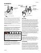
Model 110149
Model 110150
217072
217073 (shown)
LUBRICATOR
ADJUSTMENT
KNOB
AIR REGULATOR
AIR FILTER DRAIN
LUBRICATOR
ADJUSTMENT
KNOB
LUBRICATOR
SIGHT GLASS
(NOT VISIBLE FROM
THIS VIEW)
AIR REGULATOR
AIR FILTER DRAIN
To reduce the risk of serious bodily injury, including skin
injection, splashing fluid in the eyes or on the skin, or
injury from the pump starting unexpectedly, be sure
your system includes a bleed- type master air valve.
Install the air valve between the FRL outlet and the
device the FRL is serving. When relieving system air
pressure, close the bleed- type master air valve to fully
relieve air pressure.