
User's Manual

4 307–283
Installation
Notes:
T
o clean or service the filter without shutting down
the system, install a dual filter or a filter bypass as
explained below
.
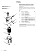
The numbers and letters in parenthesis refer to the
Figures and the Parts Drawing.
Be sure to allow 4 in. (102 mm) minimum clearance
below the filter for easier removal of the bowl (9).
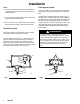
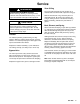
Dual Filter System
This
setup enables you to redirect the fluid to another
filter while one filter is cleaned or serviced.
Install two filters as shown in Fig. 1. Both filters must
have an adapter (A) and drain valve (B) in the filter
bowl (9) to relieve fluid pressure and drain the filter
before removing the bowl. Install four suitable shutof
f
valves (D), one at each filter inlet and outlet, to redirect
the fluid and isolate the filter when not in use.
Fig. 1
D
9
A
B
D
A
B
D
9
D
Filter Bypass System
This
setup enables you to redirect fluid through pipes
which bypass the filter
, while cleaning or servicing the
filter.
Install the filter and bypass pipes as shown in Fig. 2.
An adapter (A) and drain valve (B) must be installed in
the filter bowl (9) to relieve fluid pressure and drain the
filter before removing the bowl. Install four suitable
shutof
f valves (D), one at the filter inlet; the filter outlet;
the bypass pipe inlet; and the bypass pipe outlet, to
redirect the fluid and isolate the filter while cleaning
and servicing.
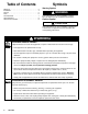
WARNING
T
o reduce the risk of component rupture and
serious injury, do not exceed the 300 psi (2.1 MPa,
21 bar) maximum working pressure of this filter
, or
the maximum working pressure of any other acces
-
sory or component in your system. Be sure that all
components and accessories are rated to with
-
stand the maximum working pressure of your
pump.
Fig. 2
D
9
B
A