
Replacement Part List
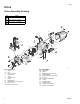
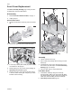
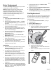
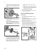
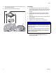

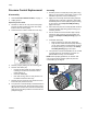

Table Of Contents

Pump
3A3951C 9
Pressure Control Replacement
Disassembly
1. Perform Pressure Relief Procedure, on page 1.
2. Unplug sprayer.
Open Easy Access Door
3. Pull tabs on sides of the easy access door pump
towards you while pushing the entire door away
from the inlet end of the pump.
4. Now lift the door so that it swivels out of the way.
5. Remove pump by sliding it off the mounting pins.
6. Remove wire shield (30).
• Unsnap the wire shield. On some models a
retaining screw must be removed from the
pump housing (1).
• Save wire shield (30).
• Note wire routing, wires on new pressure con-
trol will be routed the same way.
7. Remove the two screws (5) from electrical connec-
tor bracket (29). Save the screws.
8. Turn pressure control knob fully counterclockwise to
expose the wrench flats. Remove pressure control
(28) with wire and electrical connector bracket (29).
Verify the O-ring (28c) has been removed from the
pump housing (1).
Assembly
1. Examine pressure control (28) to verify that O-ring
(28c) is on the pressure control (28). If O-ring is not
installed on pressure control, install O-ring.
2. Apply one or two drops of thread locking adhesive
(included in kit) to threads of pressure control (28).
Assemble pressure control (28) into pump housing
(1) and torque. See Pump Assembly Drawing
page 8 for torque.
3. Route wire from pressure control (28) with electrical
connector bracket (29) along pump housing (1) to
mounting location.
4. Secure electrical connector bracket (29) to pump
housing (1) with screws (5) removed earlier and
torque. See Pump Assembly Drawing page 8 for
torque.
5. Install wire shield (30).
• Make certain wire is under wire shield (30).
• Snap the wire shield around the pump housing
(1). On some models, install retaining screw (5)
into pump housing (1) and torque. See Pump
Assembly Drawing page 8 for torque.
6. Turn pressure control knob clockwise as far as it will
go. Apply pressure control label (cl) to knob. To
position label correctly, see note below:
1
3
ti27463a
2
NOTE: When properly positioned, the function indi-
cator (fi) and hi-spray position symbol on pressure
control label (cl) are aligned.
ti28570a
c l
f i
P