
Replacement Part List
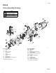
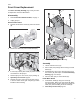
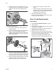
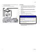

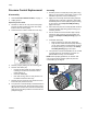

Table Of Contents

Drive
4 3A3951C
Motor Replacement
See Drive Assembly Drawing page 2 and your Own-
ers/Operation manual for illustrations.
Removal
1. Perform Pressure Relief Procedure, on page 1.
2. Unplug sprayer.
3. Remove pump assembly see Steps 3 – 5 in Pres-
sure Control Replacement page 9 disassembly
procedure.
4. Remove front cover see Front Cover Replacement
page 3 disassembly procedure.
5. Disconnect leads from ON/OFF switch (17) and
slide switch bracket (13) with ON/OFF switch (17)
out of the drive housing (1).
6. Disconnect all leads from control board (15) and
remove control board. See Control Board
Replacement page 7.
7. Remove gear and yoke (2). See Gear & Yoke
Replacement page 5.
8. Remove ground screw (18) and power cord (3) from
motor drive housing (1).
9. For sprayers with a handle (24), remove screw (6)
and handle (24) from drive housing (1).
10. Remove four screws (22) and motor (1) with drive
housing from sprayer frame.
Installation
1. Secure new motor (1) with drive housing to frame
using four screws (22) and torque. See Drive
Assembly Drawing page 2 for torque.
2. For sprayers with a handle (24), install screw (6)
and handle (24) into drive housing (1).
3. Install power cord (3) in drive housing (1), route
power cord (3) through the hole located in the bot-
tom of the drive housing (1) and around the top of
the motor shell.
4. Reconnect ground wire from power cord (3) with
screw (18) to motor drive housing (1) and torque.
See Drive Assembly Drawing page 2 for torque.
5. Slide switch bracket (13) with switch (17) into drive
housing (1).
6. Install control board (15), reconnect all wire leads
and motor connector. See Control Board Replace-
ment page 7. Refer to wiring diagram in your Own-
ers/Operation manual.
7. Install gear and yoke (2). See Gear & Yoke
Replacement page 5.
8. Install front cover see Front Cover Replacement
page 3 assembly procedure.
9. Install pump assembly see Steps 7 – 9 in Pressure
Control Replacement page 9 assembly procedure.
Fan Replacement
There are two fans used on this series of sprayers. One
is a direct drive fan (see Step 4 for replacement proce-
dure) the other is a clutch fan (see Step 5 for replace-
ment procedure).
1. Perform Pressure Relief Procedure, on page 1.
2. Unplug sprayer.
3. Remove Motor Shield page 3.
4. Direct drive fan replacement
a. Pry push nut (54b) off the motor shaft with a
small screwdriver. Discard old push nut
b. Remove fan from motor shaft.
c. Install new fan on the motor shaft with the fins
facing the motor.
d. Place a new push nut (54b) on a 3/8” or 10mm
socket.
NOTE: On hopper units you may need to remove
the hopper before replacing the motor. Direct
immersion and hopper units are easier to disas-
semble if the sprayer is placed on the side. Save all
hardware removed during disassembly, most is
required during reassembly.
ti28540a
54b
ti26471a