
Replacement Part List
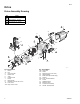
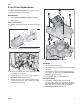


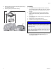

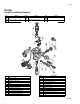
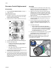

Table Of Contents

Drive
3A3951C 3
Front Cover Replacement
See Drive Assembly Drawing page 2 and your Own-
ers/Operation manual for illustrations.
Disassembly
1. Perform Pressure Relief Procedure, on page 1.
2. Unplug sprayer.
Remove Motor Shield
3. Remove two machine screws (9) and motor shield
(8).
4. Disconnect cable (10c) from control board (15).
5. If necessary remove paint shield (14). Paint shield is
not included on all sprayers.
6. Position sprayer so front cover (10) is pointing up.
7. Open Easy Access Door page 9.
8. Remove four front cover (10) screws (12) using a
T-30 Torx. Make certain gear and yoke (2) remain
installed in drive housing.
9. Pull cable (10c) through drive housing.
Assembly
1. Locate new front cover (10).
2. Route cable (10c) through drive housing to control
board (15).
3. Assemble front cover (10) to drive housing. Insert
four screws (12) and torque. See Drive Assembly
Drawing page 2 for torque.
4. Connect cable (10c) to control board (15).
Install Motor Shield
5. Install motor shield (8) using two screws (9)
removed earlier. Make sure motor shield (8) slides
into switch bracket (13). Be careful not to pinch the
cable (10c) when installing the motor shield (8).
6. Close Easy Access Door page 10.
ti28536a
9
8
10c
15
ti28537a
ti28538a
10
12
2
10c
10a