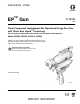
Instructions - Parts ™ EP Gun 313872B ENG Plural Component, Impingement Mix, Mechanical Purge Pour Gun with Throat Seal Liquid™ Technology For use with non-flammable foam. Not for use in explosive atmospheres. Model 257999, 24C932, 24C933, 24C934 3000 psi (20.7 MPa, 207 bar) Maximum Fluid Working Pressure 80-100 psi (0.55-0.69 MPa, 5.5-6.9 bar) Air Inlet Pressure Range 180°F (82°C) Maximum Fluid Temperature Important Safety Instructions Read all warnings and instructions in this manual.
Contents Related Manuals . . . . . . . . . . . . . . . . . . . . . . . . . . . 3 Models . . . . . . . . . . . . . . . . . . . . . . . . . . . . . . . . . . . 4 Orifice Flow Area Ratio Chart . . . . . . . . . . . . . . . 4 Fixed Orifice Flowrate Data . . . . . . . . . . . . . . . . . 5 Variable Orifice Flowrate Data . . . . . . . . . . . . . . 6 Warnings . . . . . . . . . . . . . . . . . . . . . . . . . . . . . . . . . 9 Important Two-Component Material Information 11 Isocyanate Conditions . . . . . . . . .
Related Manuals Related Manuals Manuals are available at www.graco.com. Component manuals in U.S.
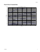
Models Models Part Purge Rod Diameter in. (mm) Orifice Size in. (mm) Handle Type 257999 0.250 (6.35) 0.031 (0.79) Handheld 24C932 0.250 (6.35) 0.031 (0.79) Auto 24C933 0.375 (9.53) 0.047 (1.2) Handheld 24C934 0.375 (9.53) 0.047 (1.2) Auto Orifice Flow Area Ratio Chart In general, flow area ratio should be equal to material ratio but will be influenced by material viscosity. The ideal flow area ratio is dependent on flow rates, material viscosity, and material ratio.
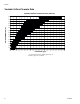
Models Fixed Orifice Flowrate Data EP Fixed Orifice Flow Data 5.00 4.75 0.086 in. Diameter Orifice 4.50 4.25 4.00 0.067 in. Diameter Orifice 3.75 3.50 3.25 0.060 in. Diameter Orifice Flow (gpm) 3.00 2.75 2.50 2.25 0.047 in. Diameter Orifice 2.00 1.75 1.50 1.25 0.031 in. Diameter Orifice 1.00 0.75 0.020 in. Diameter Orifice 0.50 0.25 0.
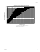
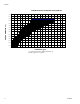
Models Variable Orifice Flowrate Data VARIABLE ORIFICE FLOWRATE DATA (1000 PSI) 0.086 0.073 0.067 0.063 ORIFICE DIAMETER (in.) 0.060 0.055 0.052 0.047 0.041 0.039 0.033 0.031 0.028 0.024 0.020 0.00 0.25 0.50 0.75 1.00 1.25 1.50 1.75 2.00 2.25 2.50 2.75 3.00 3.25 3.50 3.75 4.00 4.25 4.50 4.75 FLOWRATE (gpm) * To calculate flow in lb/min, multiply gpm rate by 10. Example: 2 gpm x 10 = 20 lb/min.
Models VARIABLE ORIFICE FLOWRATE DATA (1500 PSI) 0.086 0.073 0.067 0.063 ORIFICE DIAMETER (in.) 0.060 0.055 0.052 0.047 0.041 0.039 0.033 0.031 0.028 0.024 0.020 0.00 0.25 0.50 0.75 1.00 1.25 1.50 1.75 2.00 2.25 2.50 2.75 3.00 3.25 3.50 3.75 4.00 4.25 4.50 4.75 FLOWRATE (gpm) * To calculate flow in lb/min, multiply gpm rate by 10. Example: 2 gpm x 10 = 20 lb/min.
Models VARIABLE ORIFICE FLOWRATE DATA (2000 PSI) 0.086 0.073 0.067 0.063 ORIFICE DIAMETER (in.) 0.060 0.055 0.052 0.047 0.041 0.039 0.033 0.031 0.028 0.024 0.020 0.00 0.25 0.50 0.75 1.00 1.25 1.50 1.75 2.00 2.25 2.50 2.75 3.00 3.25 3.50 3.75 4.00 4.25 4.50 4.75 FLOWRATE (gpm) * To calculate flow in lb/min, multiply gpm rate by 10. Example: 2 gpm x 10 = 20 lb/min.
Warnings Warnings The following warnings are for the setup, use, grounding, maintenance, and repair of this equipment. The exclamation point symbol alerts you to a general warning and the hazard symbol refers to procedure-specific risk. Refer back to these warnings. Additional, product-specific warnings may be found throughout the body of this manual where applicable.
Warnings WARNING FIRE AND EXPLOSION HAZARD Flammable fumes, such as solvent and paint fumes, in work area can ignite or explode. To help prevent fire and explosion: • • • • • • • • • Use equipment only in well ventilated area. Eliminate all ignition sources; such as pilot lights, cigarettes, portable electric lamps, and plastic drop cloths (potential static arc). Keep work area free of debris, including solvent, rags and gasoline.
Important Two-Component Material Information Important Two-Component Material Information Isocyanate Conditions Spraying or dispensing materials containing isocyanates creates potentially harmful mists, vapors, and atomized particulates. Read material manufacturer’s warnings and material MSDS to know specific hazards and precautions related to isocyanates. Prevent inhalation of isocyanate mists, vapors, and atomized particulates by providing sufficient ventilation in the work area.
Important Two-Component Material Information Changing Materials • When changing materials, flush the equipment multiple times to ensure it is thoroughly clean. • Always clean the fluid inlet strainers after flushing. • Check with your material manufacturer for chemical compatibility. • Most materials use ISO on the A side, but some use ISO on the B side. • Epoxies often have amines on the B (hardener) side. Polyureas often have amines on the B (resin) side.
Throat Seal Liquid Throat Seal Liquid Disengage To disengage piston safety lock, push knob in and turn counterclockwise until it pops out. There will be a gap between knob and gun body. Read material MSDS to know specific hazards and precautions related to Throat Seal Liquid. Grounding TI14473b TI14474a FIG. 2: Piston Safety Lock Disengaged Check your local electrical code and proportioner manual for detailed grounding instructions.
Loss of Air Pressure Loss of Air Pressure Purge rod actuation is controlled by air pressure. In event of loss of air pressure, the purge rod will remain retracted, the impingement ports will remain open, and the gun will continue to pour. To stop pouring, do one of the following: • Engage piston safety lock, see Piston Safety Lock section • Close fluid valves A and B, see FIG. 3 Hook Support If necessary, use the hook support located on the top of the gun to support the weight of the gun.
Hook Support 313872B 15
Component Identification Component Identification See Parts on page 42 for part numbers and further component identification. E B A M H C J H K N D P R L F G TI14451a FIG.
Component Identification Cutaway View H J H A E B K R C D G TI14462a 313872B 17
Theory of Operation Theory of Operation Gun Triggered (Fluid Pouring) Gun Detriggered Purge rod retracts, opening the impingement ports and allowing fluid to mix and flow through the nozzle. Throat Seal Liquid lubricates the purge rod. Purge rod extends, closing the impingement ports and stopping fluid flow. Throat Seal Liquid lubricates the purge rod.
Setup Setup Perform this setup procedure to get the pour gun ready for operation. 6. Connect gun air whip hose (AA) to air quick coupler (AC). Turn on air. Open air valve (AB). See FIG. 6. 1. Close fluid valves A and B. AA AB B A AC AD TI14452a FIG. 6 TI2411a 7. Connect signal cable to solenoid valve. FIG. 5 2. Connect A and B fluid hoses to fluid manifold. 8. Models with a handle, connect signal cable to handle. 9. Disengage piston safety lock. See page 13. TI2417a 3. Engage piston safety lock.
Setup 11. Engage piston safety lock. See page 13. Adjust Orifices 12. Perform Bleed Throat Seal Liquid Cartridge procedure. See page 24. In order to balance pressures between the A component and B component the needle in each orifice may need to be adjusted. Be sure that all necessary adjustments to the proportioner are made prior to adjusting the orifices, see proportioner manual. 13. Turn on proportioner. See proportioner manual. 14. Open fluid valves A and B.
Setup Optional Hose Position As shipped, fluid inlet swivel fittings point to rear of the gun. If desired, use the following procedure to make the fluid inlet swivel fittings point downward. 5. Apply thread sealant to plugs (AH), elbows (AJ), and male threads of swivels (AE). Install elbows (AJ) in optional inlets, facing down. See FIG. 11. Install swivels in elbows. Be sure to install the A swivel in the A side. Install plugs (AH) where swivels had been. Torque all parts to 235-245 in-lb (26.6-27.
Pressure Relief Procedure Pressure Relief Procedure 7. Relieve system pressure. See Pressure Relief Procedure in proportioner manual. 8. Ensure fluid valves are closed then remove fluid manifold. 1. Engage piston safety lock. See page 13. NOTE: Air supply is required for purge rod actuation. Do not disconnect gun air supply until fluid pressure is relieved. 2. Close fluid valves A and B. Leave air valve (AB) open. 9. Place the fluid manifold over waste containers, facing away from you. 10.
Shutdown Shutdown Short Term Shutdown Long Term Shutdown Perform Short Term Shutdown procedure if gun will not be used for more than one hour. Perform Long Term Shutdown procedure if gun will not be used for more than 48 hours. 1. Perform Pressure Relief Procedure on page 22. 1. Perform Short Term Shutdown. 2. Trigger gun 3-4 times with piston safety lock engaged in order to ensure material does not build up on the purge rod.
Maintenance Maintenance Procedure Bleed Throat Seal Liquid Cartridge, page 24 Replace Mix Chamber and Front Seal, see page 30 Clean Clean Check Valves, page 27 Clean Outside of Gun, page 25 Replace Throat Seal Liquid Cartridge, page 31 Clean Breather Plug, page 26 Clean Fluid Manifold, page 26 Clean Fluid Housing Passages, page 28 Clean Orifice, page 29 Schedule Weekly Every 2-4 Weeks Monthly As Needed As Needed As Needed As Needed As Needed As Needed See Parts on page 42 for tool illustrations.
Maintenance Flush Gun NOTE: For a more thorough flush, solvent flush kits are available as an accessory. See Accessories on page 53. 1. Follow Pressure Relief Procedure, page 22. 2. Remove fluid manifold (AD). TI14470a FIG. 18: 256510, 1 qt (0.95 liter) Solvent Cup AD 7. Remove flush hoses from flush manifold. Remove flush manifold from gun. TI14457a FIG. 16 8. Remove Recirculation Block 15C850 from fluid manifold. 3. Disconnect signal cable. 9. Connect fluid manifold to gun.
Maintenance Clean Breather Plug 2. Use 5/16 in. hex nut driver to remove fluid manifold (AD). The solvents listed in this section may ignite if used in flushing. Use them only for external cleaning. Remove and clean breather plug with compatible solvent. See materials of construction info in Technical Data, page 55. The breather plug is part of the solenoid manifold assembly (30). See FIG. 19. Use N-Methylpyrrolidone (NMP), Dynasolve CU-6, Dzolv, or an equivalent to soften cured material.
Maintenance Clean Check Valves 6. Use flat tip screwdriver to pry out check valves at notch. 1. Follow Pressure Relief Procedure, page 22. 2. Flush Gun, page 25. 3. Disconnect air quick coupler (AC). Use hex nut driver to remove fluid manifold (AD). TI14464a AD AC Damaged check valve o-rings may result in external leakage. Replace o-rings if worn or damaged. 7. Press on ball (BC) to test check valve for proper movement and spring action. Replace check valve assembly if necessary. TI14463a 4.
Maintenance 11. Use hex nut driver to install fluid manifold (AD). Torque fluid manifold bolt to 20-30 in-lb (2.26-3.39 N•m). Connect air quick coupler (AC). 4. Use 5/16 in. nut driver (supplied) to remove orifices (C). See FIG. 4 on page 16. NOTICE To prevent cross-contamination of the orifices do not interchange A component and B component parts. The A component orifice is marked with an A. AK 5. Remove Front End, see page 33. AD AC 6. Remove all items from front end to enable cleaning of passages.
Maintenance Clean Orifice 1. Follow Pressure Relief Procedure on page 22. 2. Use 5/16 in. nut driver (supplied) to remove orifices (C). See FIG. 4 on page 16. NOTICE To prevent cross-contamination of the orifices do not interchange A component and B component parts. The A component orifice is marked with an A. NOTE: The cap is held in place with reverse threads. 3. Remove cap (26) from orifice (25). See Parts on page 42. 4. Remove needle (60) from orifice.
Maintenance Replace Mix Chamber and Front Seal 10. Replace front pour tip and torque to 60-70 in-lb (6.78-7.91 N•m). NOTICE 17 18 To prevent cross-contamination of the orifices do not interchange A component and B component parts. The A component orifice is marked with an A. 19 11. Replace orifices. Torque to 20-30 in-lb (2.26-3.39 N•m). 12. Perform Replace Throat Seal Liquid Cartridge, page 31. ti14469a1 1.
Repair Repair Tools Required 2. Close air valve (AB). Tools required to complete some gun repair procedures: • • • • • • • • • 15/16 in. wrench flat head screwdriver (supplied) 5/16 hex nut driver (supplied) 1/2 in. socket 3/4 in. socket 5/64 in. allen wrench (supplied) 9/64 in. allen wrench 5/32 in. allen wrench Phillips screwdriver Lubrication See Accessories on page 53 to order lubricant. Liberally lubricate all o-rings, seals, and threads. AB TI14452a FIG. 25 3.
Repair 4. Use 5/16 in. nut driver to verify Throat Seal Liquid bleed port is closed. 7. Push in and rotate cartridge 1/4 turn clockwise to lock it into gun body. TI14452a1 5. Remove plastic cap from new Throat Seal Liquid cartridge. TI14460a FIG. 29 8. Open air valve (AB). See FIG. 30. TI11340a FIG. 27 AB 6. Insert cartridge into gun body. Ensure cartridge tabs are aligned correctly with cartridge tab recesses in gun body. TI14452a FIG. 30 9.
Repair Remove Front End 7. Pull fluid housing away from gun body to remove. If fluid housing cannot be removed perform the following steps. a. Attach air quick coupler. b. Pull and release the trigger or press and release the red button on the solenoid valve. NOTICE Proper attachment of front end is critical. Do not operate gun if front end is loose or not snug against body. Improper attachment can cause slow leaks. c. Remove fluid housing. d. Disconnect air quick coupler. 1.
Repair Disassemble Front End Assemble Front End NOTICE To prevent cross-contamination of the equipment’s wetted parts, never interchange component A (isocyanate) and component B (resin) parts. The gun is shipped with the A side on the left. The fluid manifold, fluid housing, side seal assembly, check valve cartridge, and mix chamber are marked on the A side. NOTICE To prevent cross-contamination of the equipment’s wetted parts, never interchange component A (isocyanate) and component B (resin) parts.
Repair 4. Install purge rod into rear of fluid housing. Leave 3/4 in. of ball socket end of purge rod extended out of housing as shown in FIG. 31. 6. Push fluid housing flush to the gun body. Rotate fluid housing 45 degrees clockwise to engage fluid housing slots. AK 5. Install check valve assembly. See Clean Check Valves on page 27 for detailed assembly instructions. 6. Install Throat Seal Liquid bleed port screw (16b). 7. Install orifice components (25).
Repair 2. Use hex nut driver to remove fluid manifold (AD). 7. Place 1/2 in. socket on the piston shaft through the front of the gun body. Entering through the rear of the gun body, place a 3/4 in. socket with extension on the rear piston. Hold piston shaft in place and remove the rear piston. Inspect rear piston o-ring and replace if necessary. Access the Pistons and Bulkhead AD TI14463a1 Piston Shaft TI14465a 3. Disconnect signal cable. 8. Entering through the rear of the gun body, place a 3/4 in.
Repair 18. Use hex nut driver to install fluid manifold (AD). Torque fluid manifold bolt to 20-30 in-lb (2.26-3.39 N•m). Connect air quick coupler (AC). Purge Rod 1. Flush Gun, page 25. 2. Follow Pressure Relief Procedure, page 22. AD AC 3. Disconnect air quick coupler (AC). Use hex nut driver to remove fluid manifold (AD). TI14484a 19. Connect signal cable. AD AC TI14463a 4. Disconnect signal cable. 5. Remove Front End, see page 33. Inspect purge rod for wear or damage. Replace if necessary. 6.
Repair Solenoid Valve 1. Follow Pressure Relief Procedure on page 22. 2. Disconnect air quick coupler (AC). Use hex nut driver to remove fluid manifold (AD). AD AC TI14463a 3. Disconnect electronic cables from solenoid valve and handle (if installed). 4. Use 5/32 in. allen wrench to remove handle mounting plate screws. Remove handle mounting plate and handle. See Component Identification on page 16. 5. Use Phillips screwdriver to remove solenoid valve. Inspect and replace if necessary.
Troubleshooting Troubleshooting Follow Pressure Relief Procedure, page 22, before checking or repairing gun. NOTICE To prevent cross-contamination of the equipment’s wetted parts, never interchange component A (isocyanate) and component B (resin) parts. The gun is shipped with the A side on the left. The fluid manifold, fluid housing, side seal assembly, check valve cartridge, and mix chamber are marked on the A side.
Troubleshooting Problem Cause Fluid does not shut off when fluid Damaged fluid valves valves are closed Burst of air from muffler when gun is Normal triggered Steady air leakage from muffler Damaged air valve Damaged air gasket Damaged piston o-rings Leak between air cylinder and fluid Damaged o-ring housing Throat Seal Liquid cartridge installa- Friction between cartridge o-rings tion or removal is difficult and cartridge bore Throat Seal Liquid cartridge is pressure locked in cartridge bore Cannot bleed
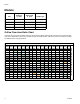
Troubleshooting Electrical Diagram 1 2 4 5 1 1 3 2 MALE 1 2 2 4 2 YE BLACK #2 3 1 5 FEMALE BLACK #1 1 3 4 5 AIR BROWN BLUE 1 1 2 2 3 3 4 4 5 5 4 5 1 1 SWITCH SIGNAL 24VDC COMMON SOLENOID ACTIVATION 4 5 1 3 3 2 MALE 313872B 2 FEMALE MALE 41
Parts Parts 3 26 1 17 16 19 6 18 3 3 21 7 22 23 3 2 20 7 1 3 Model 257999 Shown 7 5 5 24 13 2 25 16 4 9 11 1 5 29 31 3 15 6 4 30 14 32 5 3 84 10 4 34 35 3 33 12 28 3 1 Part is only included with 375 orifices. 2 Torque to 125-135 in-lb (14.1-15.3 N•m) 3 Torque to 20-30 in-lb (2.26-3.39 N•m) 4 Torque to 100-110 in-lb (11.3-12.4 N•m) 54 37 3 5 Torque to 10-12 in-lb (1.13-1.36 N•m) 6 Torque to 60-70 in-lb (6.78-7.
Parts Ref 1 2 Part 24D682 24C413 3 4 5 6 7 8 9 10 11 12 13 14 15 16 17 113003 16A425 * 15Y977 * 15Y976 * 15Y978 * 24D295 15T897 188554 121552 257979 *‡ **‡ *‡ **‡ 24D316 24D324 *** *** 18 19 20 21 22 23 24 25 ***‡ 24D325‡ 24D326 24D325 24D317 24D323 † † 26 † † 28 313872B 246012 Quantity 257999, 24C933, EP Gun, 250, 24C932, EP Gun, 375, 24C934, 0.031 in. EP Gun, 250, 0.047 in. EP Gun, 375, orifice, 0.031 in. orifice, 0.047 in.
Parts Ref 29 30 31 32 33 34 35 36 37 41 43 44 45 46 47 48 49 51 52 54 Part 24D315 257977 106245 24D318 24D319 Description GASKET, solenoid, manifold MANIFOLD, solenoid, assy SCREW, socket head cap VALVE, solenoid, 4 way CORD SET, euro/male, din/female 15Y968 PLATE, adapter, handle 15D256 SCREW, socket head cap 24D073 HANDLE, 2k dispense C19980 SCREW, cap, socket hd 172479 ▲ TAG, warning 112307 ELBOW, street 117510 COUPLER, line, air, 1/4 npt 15B772 HOSE, air, 18 inch 15B565 VALVE, ball 117661 PIN, vise 1
Kits Kits See Maintenance on page 24 and Repair on page 31 for appropriate kit installation procedures. See Complete O-ring Placement Guide on page 52 for o-ring identification help.
Kits Kit Description 250 Orifice 375 Orifice Orifice O-Ring Kit Parts included in Kit Kit Number Description Qty 24C751 24C756, 24C805 24C815; see Orifice Kits on page 50 Orifice Housing 1 O-Ring 1 O-Ring 1 O-Ring 1 Needle 1 Backup Ring 1 O-Ring 1 Orifice Cap 1 Cleanout Drill 1 Orifice Housing 1 O-Ring 1 O-Ring 1 O-Ring 1 Needle 1 Backup Ring 1 O-Ring 1 Orifice Cap 1 Orifice Spacer 1 Cleanout Drill 1 O-Ring 1 O-Ring 1 O-Ring 1 O-Ring 1 24C761 24C766, 24C7
Kits Kit Description Iso Check Valve Check Valve Parts included in Kit Kit Number Description Qty 246731 Check Valve Housing 1 Spring Retaining Screw 1 Carbide Ball 1 Filter 1 Check Valve Spring 1 O-Ring 1 O-Ring 1 Check Valve Housing 1 Spring Retaining Screw 1 Carbide Ball 1 Filter 1 Check Valve Spring 1 O-Ring 1 O-Ring 1 246352 40 Mesh Filter Kit (40 mesh, 0.015 in., 375 micron) 246357 40 Mesh Screen 10 60 Mesh Filter Kit (60 mesh, 0.010 in.
Kits Kit Description Parts included in Kit Kit Number Description Qty Check Valve Face O-Ring Kit 248133 O-Ring 6 250 Fluid Housing Seals 24D313 Housing Outer O-Ring 1 Housing Inner O-Ring 1 Outer Fluid Housing O-Ring Kit 24E611 O-Ring 6 Inner Fluid Housing O-Ring Kit 256773 O-Ring 6 250 Lip Seal 24E252 250 Lip Seal 6 O-Ring 6 375 Lip Seal 24D325 375 Lip Seal 6 Piston Seals 24D312 Rod O-Ring 3 Front Piston O-Ring 1 Bulkhead O-Ring 1 Rear Piston O-Ring 1 48 Illustra
Kits Kit Description Parts included in Kit Kit Number Description Piston Safety 24D295 Stop Stop Shaft O-Ring Kit 257425 Qty Back Cap 1 O-Ring 1 Piston Stop 1 Safety Stop Shaft 1 O-Ring 1 Spring 1 O-Ring 6 Illustration Located inside back cap Handle Trigger Switch Harness Fluid Housing Kit 313872B 24D073 2K Electric Handle 1 Handle Mounting Screw 4 Trigger Switch 1 Switch Spacer 1 Air Valve Plug 1 Strain Relief 1 Signal Cable 1 24D680 250 Fluid Housing 1 24D681 3
Kits Kit Description TSL Check Valve Kit Parts included in Kit Kit Number Description Qty 24B843 Check Valve Seat 1 Ball 1 Spring 1 O-Ring 1 Illustration Orifice Kits In the following table, shaded rows indicate “Super Standard” items that are typically stocked and provide the best delivery dates. Impingement Kit Type and Kit Number Port Size 250 Model Polyol 250 Model Iso 375 Model Polyol 375 Model Iso in. mm Orifice Kit Orifice Kit Orifice Kit Orifice Kit 0.016 0.
Kits Drill Bit Kits For cleaning fluid housing passages and orifices. Drill bit illustrations are actual size for comparison. See Clean Fluid Housing Passages on page 28. Not all sizes are used with every gun model. Orifice Size Kit Number Drill Bit Size Qty in Kit in. mm 24D289 #78 6 0.016 0.41 246631 #76 6 0.020 0.51 246815 #73 6 0.024 0.61 248892 #70 6 0.028 0.71 24D293 #68 6 0.031 0.79 24D294 #65 6 0.035 0.89 248640 #61 6 0.039 0.99 246629 #58 6 0.042 1.
Kits Complete O-ring Placement Guide The following illustration shows all gun o-rings at actual size. See Kits on page 45 for o-ring kit details including quantities of each o-ring in each kit.
Accessories Accessories Lubricant for Gun Rebuild NOTICE Use only Throat Seal Liquid on the o-rings, seals, and threads of the Throat Seal Liquid cartridge. Fusion grease or other petroleum-based or vegetable-based lubricants will cause cartridge o-rings and seals to swell and stick. Flushing Manifold 15B817 Manifold Block Attaches to gun fluid manifold to enable flushing. ti2647a 248279, 4 oz (113 gram) [10] High adhesion, water resistant, lithium-based lubricant. MSDS sheet available at www.graco.com.
Accessories Solvent Flush Canister Kit 256510, 1 qt (0.95 liter) Solvent Cup Includes flushing manifold to flush gun with solvent. Portable for remote flushing. See manual 309963. TI14470a Solvent Flush Pail Kit 248299 5.0 gal. (19 liter) Pail Includes flush manifold with individual A and B shutoff valves, and air regulator. See manual 309963.
Technical Data Technical Data Maximum Fluid Working Pressure . . . . . . . . . . . . . . . . Minimum Air Inlet Pressure. . . . . . . . . . . . . . . . . . . . . . Maximum Air Inlet Pressure . . . . . . . . . . . . . . . . . . . . . Maximum Fluid Temperature . . . . . . . . . . . . . . . . . . . . Air Inlet Size . . . . . . . . . . . . . . . . . . . . . . . . . . . . . . . . . A Component Inlet Size . . . . . . . . . . . . . . . . . . . . . . . . B Component Inlet Size . . . . . . . . . . . . . . . . . . .
Technical Data Dimensions A C B Side View TI14487a E D TI14488a Bottom View F Ref Dimension, in. (mm) A 10.8 (274) B 11.7 (297) C 6.1 (155) D 3.1 (79) E 0.73 (19) F 1.
Technical Data 313872B 57
Graco Standard Warranty Graco warrants all equipment referenced in this document which is manufactured by Graco and bearing its name to be free from defects in material and workmanship on the date of sale to the original purchaser for use. With the exception of any special, extended, or limited warranty published by Graco, Graco will, for a period of twelve months from the date of sale, repair or replace any part of the equipment determined by Graco to be defective.