
Monitor Controller Owners Manual
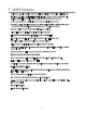
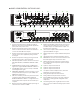
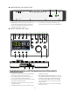
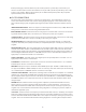
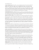
Table Of Contents
- 1 Welcome
- 2 Important Safety Information
- 3 Safety Marking Symbols
- 4 Service Information
- 5 m905 features
- 7 Unpacking and Installing
- 8 Connecting the m905
- 9 Normal Operation Mode
- 10 Setup Mode
- 11 General Setup
- 12 ABOUT CROSS-FEED
- 13 Communication Error Handling
- 14 Computer Audio Setup
- 15 Updating Firmware
- 16 Specifications
- 17 Block Diagram
- 18 PCB Jumper Locations
- 19 Wiring Diagrams
- 20 Cleaning and Maintenance
- 21 Warranty Information
- 22 Manual Revisions

5
M905 AUDIO CONTROL UNIT REAR PANEL
24
REMOTE
TALKBACK SWITCH
CUE INSPEAKER 1 BALANCED IN
L
R
TALKBACK MIC IN
S/PDIF AES3
AES 2AES 1 S/PDIF TOSLINK
UNBAL IN
WORDCLOCK
UPGRADE
ADAT USB 2
SPEAKER 2 SPEAKER 3
1M
75
TALKBACK OUT
SUB/
DAC OUT
CUE OUT
L
R
L
R
DIGITAL IN
DIGITAL OUT
RoHS
COMPLIANT
Pb
100-240 VAC / 50-60Hz
60 Watts Max
OUT
IN
L
R
L
R
L
R
L
R
L
R
GRACE DESIGN
LYONS, CO USA
1
2
3
4
5
6
7
8
9
10
11
20 21 23
12
16 17 18 19
13
14 15
22
BALANCED IN 2
L
R
REMOTE
TALKBACK SWITCH
CUE INSPEAKER 1 BALANCED IN
L
R
TALKBACK MIC INUNBAL INUPGRADE SPEAKER 2 SPEAKER 3
TALKBACK OUT
SUB/
DAC OUT
CUE OUT
L
R
L
R
RoHS
COMPLIANT
Pb
100-240 VAC / 50-60Hz
60 Watts Max
L
R
L
R
L
R
L
R
L
R
GRACE DESIGN
LYONS, CO USA
1 AC mains input universal 100-240 VAC, 50-60Hz, 60
Watts max. This connects m905 (with the supplied AC
power) cable to AC power source.
2 Word Clock termination switch used to properly ter-
minate a connection from an external clock reference
source to the m905 Word Clock input.
3 Word Clock input for incoming word clock signals from
a master clock or other equipment passing a master
clock signal.
4 Word Clock output for sending or passing word clock
signals from the m905 to other equipment.
5 Two AES3 input XLR connectors used to receive stereo
AES3, Dual Wire AES3, and DSD64 or DSD128 via DoP
V1.1
6 */PDIF INPUT RCA jack input accepts a S/PDIF format
digital stereo signal or DSD64 or DSD128 via DoP V1.1
7 TOSLINK INPUT Optical connector accepts a TOSLINK
format digital stereo signal.
8 ADAT INPUT LIGHTPIPE™ connector provides a 2 chan-
nel input selectable in 4 pairs (or 2 pair S/MUX) of an
ADAT format digital source.
9 USB Class 2 interface provides an asynchronous mode
computer interface PCM up to 24bit/196kHz and
DSD64 and DSD128 via DoP V1.1. Configured for two
channels down from computer and 10 channels up to
computer.
10 Digital out provides a buffered digital loop-through of
a selected source via AES or S/PDIF.
11 Multi-mode SUB / DAC / Meter output can be used as
either a subwoofer output (mono or stereo), a fixed
level DAC output, or a dedicated meter output. Con-
figurable in the setup menu.
12 Cue out stereo output includes sum of the CUE input
signal with talkback mic signal.
13 Talkback output mono output of talkback microphone
signal.
14 USB upgrade port for future ACU firmware revisions.
15 DB15 Remote connector connects the m905 ACU and
RCU with supplied 15 pin serial remote cable
16 Talkback switch input, momentary or latching opera-
tion, configured in the setup menu.Speaker 1 output
stereo balanced
17 Speaker 1 output stereo balanced
18 Speaker 2 output stereo balanced
19 Speaker 3 output stereo balanced
20 Cue input for studio headphone mixes, sums with
talkback mic signal for CUE output.
21 Analog Balanced Input via XLR connectors.
22 Analog Unbalanced input via RCA connectors.
23 External Talkback mic input, for any type of external
microphone, 7-70dB gain, 48V configurable in the
setup menu.
24 m905 Analog Rear panel - digital inputs are not avail-
able - a second set of balanced Analog inputs via XLR
is installed.