
Monitor Controller Owners Manual
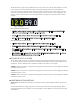
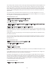
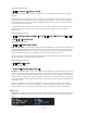
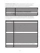
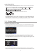
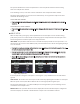
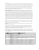
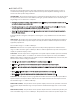
Table Of Contents
- 1 Welcome
- 2 Important Safety Information
- 3 Safety Marking Symbols
- 4 Service Information
- 5 m905 features
- 7 Unpacking and Installing
- 8 Connecting the m905
- 9 Normal Operation Mode
- 10 Setup Mode
- 11 General Setup
- 12 ABOUT CROSS-FEED
- 13 Communication Error Handling
- 14 Computer Audio Setup
- 15 Updating Firmware
- 16 Specifications
- 17 Block Diagram
- 18 PCB Jumper Locations
- 19 Wiring Diagrams
- 20 Cleaning and Maintenance
- 21 Warranty Information
- 22 Manual Revisions

17
ANALOG ONLY OPTION
The m905 is now available without the built in Digital to Analog converter section. The Analog version
may updated to the Digital version at any time.
• Inputs are shown across the bottom and are (in this order) balanced, balanced 2, unbalanced and cue
• Inputs across the top are dark gray and pressing the associated input button has no response.
• The first input button in the upper left indicates “no dac”
• In SUB/DAC/MTR SETUP, the “dac output” option for output mode is removed
• DIGILOOP SETUP is removed
• DIGITAL I/P SETUP is removed
Important Note: The m905 Analog ships with a standard ethernet cable for connecting the RCU. This cable
does not carry the headphone signal to the RCU, so the headphone jack on the RCU will be deactivated and
a small jack plug will be installed. If you wish to use the headphone jack on the RCU, you will need to buy the
remote cable upgrade from your Grace Design Dealer or directly from the Grace Design Factory.
10 Setup Mode
ENTERING AND EXITING SETUP MODE
Pushing the ‘setup’ button enters the m905 into setup mode. This is indicated by the display showing
the m905 setup mode screen and the setup button ashing white. In this mode, the user can congure
all of the adjustable system parameters, while still having access to most of the normal mode features.
<figure - Setup Screen>
From this screen, pushing any hardware switch will enter that features individual setup menu. From
here, rotating the knob clockwise moves the white highlighted selection down. Rotating it counter-
clockwise moves the white highlighted selection up. In some cases there may be more parameters than
can be displayed at one time on the screen. If this is the case, the display indicates this by placing a little
up or down arrow on the right edge of the display.
<figure setup screen selection >
Unless otherwise noted, pressing the knob enters the parameter edit mode. This is indicated by the
parameter changing from black to red on the display. Rotating the knob in edit mode modies the se-
lected parameter. Pressing the knob again exits edit mode and returns to the parameter selection menu.