
Monitor Controller Owners Manual
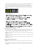
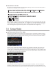
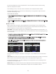
Table Of Contents
- 1 Welcome
- 2 Important Safety Information
- 3 Safety Marking Symbols
- 4 Service Information
- 5 m905 features
- 7 Unpacking and Installing
- 8 Connecting the m905
- 9 Normal Operation Mode
- 10 Setup Mode
- 11 General Setup
- 12 ABOUT CROSS-FEED
- 13 Communication Error Handling
- 14 Computer Audio Setup
- 15 Updating Firmware
- 16 Specifications
- 17 Block Diagram
- 18 PCB Jumper Locations
- 19 Wiring Diagrams
- 20 Cleaning and Maintenance
- 21 Warranty Information
- 22 Manual Revisions

11
talkback function can be activated at both the RCU and the remote switch. See the remote talkback cable
diagram at the end of this manual for connection details.
9 Normal Operation Mode
m905 operation is categorized in two dierent modes: normal operation mode and setup mode. Once
the RCU and ACU are connected and power is turned on, the system boots up into normal operation
mode.
In normal operation mode, all of the ACU controls are active and the LCD display shows the main oper-
ating screen with input, level, SPL and DAC status. Setup mode is entered by pushing the ‘setup’ button,
which switches the LCD display to the setup menu. Upon entering setup mode, current monitoring
function is preserved, but the display and controls will be dedicated to setup menu navigation and
input.
The m905 is a closed loop control system to ensure that the status reported on the RCU matches the ac-
tual hardware setting in the ACU. Any changes made to the conguration of the system are transmitted
to the ACU where they are processed and reported back to the RCU for conrmation. In the following
sections all of the controls and features of the normal operation mode are detailed.
INPUT SELECTION
The RCU features 8 dedicated input select buttons, in 2 rows of 4, above and below the LCD display. The
m905 Analog has 4 dedicated input select buttons along the bottom of the LCD display. Pressing any
of these buttons will select the associated input source and connect it to the main monitor path. The
currently selected input source is indicated by the blue input icon on the LCD, while inactive inputs
are indicated by the gray input icons. NOTE: The displayed name is user congurable in setup mode. The
names used here are the defaults.
UNBALANCED Selects the unbalanced analog input for the monitoring path.
BALANCED Selects the balanced analog input for the monitoring path.
BALANCED 2 (m905 Analog only) Selects the second balanced analog input for the monitoring path.
CUE Selects the balanced cue analog input for the monitoring path.
TOSLINK Selects the TOSLINK digital input for the monitoring and DAC path.
ADAT / AES DW When ADAT mode is active - Selects the ADAT digital input for the monitoring and DAC
path. Once selected, pressing the ADAT input button again increments sequentially through the channel
pairs (1-2, 3-4. 5-6, 7-8 for regular ADAT and 1-2, 3-4 for S/MUX ADAT). When AES Dual Wire mode is active
(congured in SETUP), selects the AES Dual Wire input for monitoring and DAC path. Note that AES Dual
Wire mode requires moving a jumper on the m905 digital PCBA inside the unit. See AES DW Setup in sec-
tion 9 of this manual for details.
S/PDIF Selects the S/PDIF digital input for the monitoring and DAC path.
AES1 / AES2 Selects the AES1 or AES2 digital input for the monitoring and DAC path. Once selected,
pressing the AES input button again toggles the AES1 or AES2 selection. The system remembers the last
AES input that was selected (as indicated by the input icon display).
USB Selects the USB digital input for the monitoring and DAC path.
VOLUME CONTROL, PRESET & HEADPHONE MUTE