
Monitor Controller Owners Manual
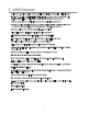
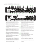
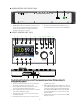
Table Of Contents
- 1 Welcome
- 2 Important Safety Information
- 3 Safety Marking Symbols
- 4 Service Information
- 5 m905 features
- 7 Unpacking and Installing
- 8 Connecting the m905
- 9 Normal Operation Mode
- 10 Setup Mode
- 11 General Setup
- 12 ABOUT CROSS-FEED
- 13 Communication Error Handling
- 14 Computer Audio Setup
- 15 Updating Firmware
- 16 Specifications
- 17 Block Diagram
- 18 PCB Jumper Locations
- 19 Wiring Diagrams
- 20 Cleaning and Maintenance
- 21 Warranty Information
- 22 Manual Revisions
10
anced equipment. (p.37)
SUB / DAC / METER OUTPUT Meter OUTPUT – Can be congured as either two mono balanced subwoofer
outputs, one stereo subwoofer output, a stereo balanced xed DAC output, or a stereo balanced con-
gurable meter output.. These output options are congurable in the setup menu. Subwoofer outputs
settings are congured with each speaker output. As a DAC out, the last selected digital input is converted
and sent to this output at all times. Typically this output is used to utilize the high performance m905 DAC
when connected to an analog mastering deck or other analog outboard gear. The meter output can be
congured at a xed level or to follow the speaker monitoring level. Connections are made with standard
balanced XLR cables. Connectors are wired pin 1 shield, pin 2 positive pin 3 negative.
STEREO HEADPHONE OUTPUTS HEADPHONE outputs are provided via ¼” TRS (Tip, Ring, Sleeve) jacks, one
on the frontpanel of the ACU and the other on the RCU (RCU cable upgrade required for m905 Analog units).
These outputs are wired in parallel. The headphone output amplier is capable of delivering very high cur-
rents to the headphones and can drive loads down to 25 Ohms.
DIGITAL OUTPUTS AES3, S/PDIF Two stereo digital (loop-thru) outputs are provided via AES3 XLR and S/
PDIF RCA connectors. These provide a buered output of a user selectable digital input. Use of high qual-
ity 110 Ohm balanced cable for the AES3 out 75 Ohm cable for the S/PDIF out is highly recommended.
WORDCLOCK IN The m905 can accept a Word Clock signal from an external clock generating unit via this
BNC connector. This might be a stand-alone clock source or via, for example, the Word Clock output from
your digital audio workstation. It should be noted that referencing the m905 from an external Word Clock
is not necessary for the unit to function properly as the m905 will also function very well by stripping
embedded clock data from a connected digital audio source. However, you may have your entire digital
audio system referenced from a single master clock, hence the ability for the m905 to receive and lock
itself to this clock.
WORDCLOCK OUT The Word Clock output allows the user to synchronize other digital audio equipment to
the m905. It functions in two modes: When monitoring a digital input with the clock source set to “word
clock” the word clock output will be a buered copy of the word clock input. If the input being monitored
is not set to have word clock as the clock source then the word clock output will be the clock recovered
from the the incoming digital audio data stream. In the case of USB the word clock output will be derived
from the m905 internal clock. The output is buered and is designed to drive a 75 Ohm line.
WORD CLOCK LOAD SWITCH The switch labeled 1M Ohm/75 Ohm is used to terminate the Word Clock
input. If the Word Clock signal in your studio is being daisy-chained from unit to unit (including the m905),
you’ll want to set the switch to 1M Ohm, which is essentially an unloaded setting. If the m905 is the only
device being clock referenced (or the last unit in a daisy-chain of other high impedance units), you’ll want
to select the 75 Ohm load position for proper termination. NOTE: Selecting the 75 Ohm load position when
there is already another device on the line that has a 75 Ohm load will create a total load of 37 Ohms, which
will attenuate the signal to a point where the m905 may not lock.
REMOTE CONNECTOR The m905 RCU handles all system control. Connection to the m905 RCU is via this
DB15 connector, which carries RS422 serial data, DC power and headphone signals. The m905 ships with
a high quality 25’ cable. While the serial data can travel over 1000 feet we do not recommend cables
longer than 50’ for headphone use. Be sure to use the supplied DB15 cable. If you need a longer, cable
contact your Grace Design dealer or us directly. Do not use an o the shelf DB15 cable as the pinout will
be incompatable. Important Note: The m905 Analog ships with a standard ethernet cable for connecting
the RCU. This cable does not carry the headphone signal to the RCU, so the headphone jack on the RCU will be
deactivated and a small jack plug will be installed. If you wish to use the headphone jack on the RCU, a cable
upgrade is available for purchase from your Grace Design Dealer or directly from the Grace Design Factory.
TALKBACK SWITCH The talkback switch input allows the connection of an external switch, such as a
footswitch, for remotely activating the talkback mic input, or the built in talkback mic on the RCU. The
input is a TRS jack and is used with a “normally open” switching device. Note that when using this jack the