
Owner's Manual


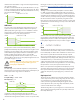


Table Of Contents

9
9.12 FOOTSWITCH CONTROLS
Boost / FX
This switch has two dierent functions based on the setting of
DIP switch #6 labeled FS2.
In the Boost setting (switch in the down position), the
footswitch enables the boost circuit. When active, the LED will
be lit and the output signal is boosted by the amount set by the
‘BOOST’ knob. More is always better, but feedback and angry
soundpeople can make for an uncomfortable gig, so start small!
In FX setting, (switch in up position) the footswitch activates or
deactivates the insert / FX loop. There are 2 dierent modes for
operating the FX footswitch:
• Mutes the return of the FX loop, so whatever signal is
still in the FX loop (i.e. reverb or delay tails) will be cut
immediately.
• Mutes at the send of the FX loop, allowing signals (i.e.
reverb or delay tails) in the FX loop to trail o naturally.
These two options are selected via the internal Jumper J10.
Also, remember, if you are using the Boost footswitch for FX
insert control, you can also turn on the ‘Boost Trim Function’ via
internal jumper J2, which allows you to use the Boost control
knob as an addition 10dB gain / trim control.
Mute / Tune
This switch mutes the DI and AMP output, but not the tuner
output. This enables you to quickly and easily cut your signal
to the FOH or stage amp and tune or unplug your instrument
without having to have the soundperson mute your channel.
When MUTE / tune is active, the adjacent LED illuminates RED.
9.13 SIDE PANEL CONTROLS
ROXi has a lot going on, more than we could t on the rear and
top panels alone. So there are a few features to be familiar with
on the side panel.
DIP Switches
This is a bank of 6 DIP switches, used to activate these various
modes and settings.
1. DI output level switch (MIC and LINE)
2. High Pass Filter roll o select (75Hz or 125Hz)
3. High Pass Filter on/o
4. 12 Volt phantom power on/o
5. 9V output on/o
6. Footswitch 2 function, boost or insert
DIP switches are a little hard to move, which is good because
they probably won’t get inadvertently changed, but bad when
you actually want to use them. Use the edge of a ngernail, a
guitar pic or a toothpick. Whatever you chose, take care not to
dig into the plastic too hard. You’ll get the hang of it.
10 Diagrams
10.1 BLOCK DIAGRAM
ISO OUTPUT TRANSFORMER
GAIN
LOW BAND
BOOST / CUT
HIGH BAND
BOOST / CUT
MID BAND
BOOST / CUT
BOOST GAIN
HPF
HPF
SIG / CLIP INDICATOR
FREQ SEL
ON/OFF
ISO MIC / LINE LEVEL
SIDE PANEL DIP SWITCH
REAR PANEL PUSHBUTTON SWITCH
BOOST / INSERT
MUTE / TUNE
FRONT PANEL KNOB
FOOTSWITCH
CONTROL TYPES:
INSERT SEND PAD
INTERNAL JUMPER SETTING
9V 2.1mm CENTER = NEG OUTPUT
9V @ 500mA
POWER SUPPLY
POLARITY
BALANCED XLR MIC INPUT
1/4" HI-Z UNBALANCED IN
+48V PHANTOM POWER
LINE / MIC
+48V ON/OFF
TIP
+12V MIC POWER
(TIP / RING / OFF VIA JUMPER)
+12V ON/OFF
LO/HI GAIN
VIA JUMPER
LO/HI RANGE
LO/HI RANGE
BOOST / INSERT
9V ON / OFF
500mA MAX
EFX MIX
MID BAND
FREQ SELECT
INSERT RETURN
MUTE BYPASS
AMP BALANCED OUT
ISO BALANCED OUT
TUNER UNBALANCED OUT
INSERT SEND
INSERT RETURN
0, -6dB, -12dB
AMP OUTPUT LEVEL
GROUND LIFT