
Install Instructions


7
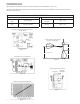
FLOAT SWITCH AND PANEL CHART
The purpose of this chart is to show the required switch
quantities and the function of each switch in a typical
wastewater system. The quantities required vary de-
pending on the switch type, single-action or wide-angle.
Switch quantities also vary by panel type: simplex with
and without alarms, and duplex with alarms.
Duplex Panels using single-action switches:
Three Float Panel Wiring
SW1 Bottom Pumps Off
SW2 Middle 1st Pump On
SW3 Top 2nd Pump & Alarm On
Four Float Panel Wiring ➁
SW1 Bottom Pumps Off
SW2 2nd 1st Pump On
SW3 3rd 2nd Pump On
SW4 Top Alarm On
Duplex Panels using wide-angle switches:
Three Float Panel Wiring
SW1 Bottom 1st Pump On/Both Off
SW2 Top 2nd Pump & Alarm On
Four Float Panel Wiring
SW1 Bottom 1st Pump On/Both Off
SW2 Middle 2nd Pump On
SW3 Top Alarm On
Simplex Panel using single-action switches:
Simplex Panel with Alarm ①
SW1 Bottom Pump Off
SW2 Middle Pump On
SW3 Top Alarm On/Off
Simplex Panel with No Alarm
SW1 Bottom Pump Off
SW2 Top Pump On
Simplex Panel using wide-angle switches:
Simplex Panel with Alarm
SW1 Bottom Pump On/Off
SW2 Top Alarm On/Off
Simplex Panel with No Alarm
SW1 Pump On/Off
Inlet
Alarm SW3
Pump On SW2
Pump Off SW1
Discharge
Inlet
Alarm SW4
Lag Pump On
SW3
Pump Off
SW1
Discharge
Lead Pump On
SW2
Simplex ➀
Duplex ➁