
Quick Install Guide

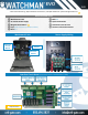
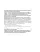

Interface Wiring Diagram (Oriented the same as the Watchman install)
❶ Wire main power from the transformer to the power connector on the
circuit board.
❷ Connect gate trigger wires from the Normally Open (NO) and Common (C)
to the free-exit or exit terminals on the gate operator.
❸ Connect the gate status wires on the 6-pin connector on the main relay
and input plug to the magnetic switch or a Dry Contact, Normally Closed (NC)
relay on the gate operator.
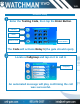
❹ If using an optional 26-bit reader (ex., keypad, card reader, RFID, or
clicker), wire the device to the Wiegand connection on the interface circuit
board.
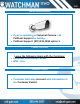
❺ Use Camera Guide if adding optional external camera.
❻ Test/activate using the test credentials on the Activation & Test Process
document.
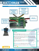
6-Wire Installation Instructions
Important Item
❶
❷
❹
❸
WXL