
Datasheet


GMC-I Messtechnik GmbH 5
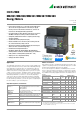
ENERGYMID
EM2281/EM2289/EM2381/EM2387/EM2389
Energy Meters
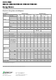
Standard Meters with MID Approval and Initial Calibration, (available from stock)
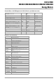
Abbreviations and Their Meanings
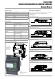
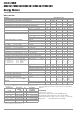
Direct connection, 5(80) A, class B, MID for
4-wire systems, 3 x 230 / 400 V
Feature Standard
(M0)
Multifunctional variant
(M1)
Programmable S0 pulse rate V2, P0, U6 U2289-V012 U2289-V022
LON W1, P0, U6 U2289-V013 U2289-V023
M-Bus W2, P0, U6 U2289-V014 U2289-V024
TCP/IP (BACnet, Modbus TCP, HTTP) W4, P0, U6 U2289-V017 U2289-V027
Modbus RTU W7, P0, U6 U2289-V018 U2289-V028
Transformer connection, 5(6) A and 1(6) A
, class B, MID for
3-wire systems, 3 x 230 / 400 V, programmable CT / VT
Feature Standard
(M0)
Multifunctional variant
(M1)
Programmable S0 pulse rate V2, P0, U6, Q1 U2387-V012 U2387-V022
Transformer connection, 5(6) A and 1(6) A
, class B, MID for
4-wire systems, 3x 230 / 400 V, programmable CT / VT
Feature Standard
(M0)
Multifunctional variant
(M1)
Programmable S0 pulse rate V2, P0, U6, Q1 U2389-V011 U2389-V021
LON W1, P0, U6, Q1 U2389-V016 U2389-V026
M-Bus W2, P0, U6, Q1 U2389-V015 U2389-V025
TCP/IP (BACnet, Modbus TCP, HTTP) W4, P0, U6, Q1 U2389-V017 U2389-V027
Modbus RTU W7, P0, U6, Q1 U2389-V018 U2389-V028
Symbol Meaning
CT
Current transformation ratio
CT × VT Product of CT times VT
EPtot Total effective energy (for all phases)
EQtot Total reactive energy (for all phases)
f Frequency
I1, I2, I3 RMS current value per phase
I
N
I
N
: N conductor current (calculated)
I
max
Limit current
I
min
Minimum current value
I
ref
Reference current (value)
M1 (feature) Multifunctional variant: measurement of U, I, P, Q, S, PF, f,
THD, In
M2 (feature) Measurement of reactive energy
M3 (feature) Multifunctional variant: measurement of U, I, P, Q, S, PF, f,
THD, In, reactive energy
P1, P2, P3, Ptot Active power, per phase and total
PF1, PF2, PF3, PFtot Power factor (cos phi), per phase and total
Q1, Q2, Q3, Qtot Reactive power, per phase and total
Q1 (feature) Programmable transformation ratios
Q9 (feature) Fixed transformation ratios
S1, S2, S3, Stot Apparent power, per phase and total
SØ Pulse rate, SØ output
THD I1, I2, I3 Current distortion component per phase
THD U1, U2, U3 Voltage distortion component per phase
U
n
Reference voltage
U1
N
, U2
N
, U3
N
Star voltage (RMS)
U12, U23, U13 Delta voltage (RMS)
V2/V4 (feature) Programmable SØ
V9 (feature) Customer-specific SØ rate
VT Voltage transformation ratio
W1 ... 7 (feature) Bus connections
Z1 (feature) Load profile (only possible with bus)