
User manual


90 GMC-I Messtechnik GmbH
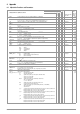
8.7 System Messages
Error messages may appear at the digital display immediately
after the device is switched on, or after manual or remote control
triggering of certain functions.
Code Meaning / Cause Remedy
Err 1 ROM checksum error
ROM memory test failed
The device must be tested at a service
center and repaired if necessary.
Err 2 RAM write/read error.
RAM memory test failed
The device must be tested at a service
center and repaired if necessary.
Err 4 Write/read error.
Initialization of the IEC bus interface
failed:
– Electrical isolation, optocoupler
– Auxiliary power
– Controller
The device must be tested at a service
center and repaired if necessary.
Err 11 After execution of the self-test
(manual).
The measured value of the
manipulated parameter was
compared with the numeric setpoint
at the momentary operating point with
activated output and a deviation of
> n resolution was detected (n is
defined internally, U: 15 LSD; I: 30
LSD).
➭ CAL
The device must be tested at a service
center and repaired if necessary.
Err 3 An unspecified self-test sub-function
has failed.
The device must be tested at a service
center and repaired if necessary.
Err 7 Serial interface disabled,
impermissible configuration, e.g. 8DB,
PE, 2SB, or 7DB, PN, 1SB. The error
message is displayed during the
power-up routine, or under the “BUS”
menu item after each entry.
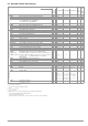
Err 20 Attempted deletion and insertion
outside of the defined memory range
(from start to stop address).
Err 21 Error message during SEQUENCE
function operation, or after RECALL:
The (next) voltage or current setpoint
value to be recalled from the
SEQUENCE memory is higher than the
respective limit value (USET > ULIM or
ISET > ILIM). For this reason, memory
recall cannot be executed. The
SEQUENCE run is aborted.
Check the contents of the SEQUENCE
to be executed and coordinate
setpoints and limit values.
Err 22 Error message after SEQUENCE GO:
No executable values exist within the
memory range defined by the START
and STOP addresses for the
SEQUENCE run. The SEQUENCE run
cannot be started.
Check the selected START and STOP
addresses, as well as the contents
(USET, ISET and TSET) of the memory
locations defined by these
parameters.
Err 24 Attempted recall of an invalid value
(remote: *RCL xxx, where 011 xxx
255).
Err 25 Error message after OUTPUT ON:
Activation of the output is disabled by
an OUTPUT OFF signal at the trigger
input of the analog interface.
In order to activate the output, either
the trigger control signal must be set
to low, or trigger input action must be
set to another function, after which
the OUTPUT ON command must be
re-executed.
Err 31 CMD error (remote)
Err 32 CMD error (remote) Adhere to calibration sequence
Err 33 Uoff, Ufs
➭ Device must be in voltage
regulating mode
e.g. eliminate short-circuit or reduce
load
Err 34 Iff, Ifs
➭ Device must be in current
regulating mode
e.g. increase load or short circuit the
output terminals
Err 35 Inadequate balancing range – Check entered data
– Hardware error?
Err 36 Calibration error:
An uncorrected error has occurred, no
CAL data could be saved.
Additional message(s):
40 U_offset setpoint
41 U_offset measured value
42 U_full-scale setpoint
43 U_full-scale measured value
44 I_offset setpoint
45 I_offset measured value
46 I_full-scale setpoint
47 I_full-scale measured value
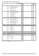
Err 99 POWERFAIL
Voltage dip has occurred at auxiliary
supply power
➭ RE-START
+OL or
–OL
Display indicates measuring function
over-ranging:
If measured output voltage UOUT or
output current IOUT violates the
specified range (
➭ chapter 1.5.3),
+OL or –OL appears at the display.
The appearance of this message
always indicates that the specified
limit values for output voltage or
current have been violated.
Examples:
UOUT indicates +OL: e.g. caused by
overdriving output voltage with an
analog control signal applied to the
analog interface.
UOUT indicates –OL: due to
incorrectly connected sensing leads.
IOUT indicates +OL: e.g. caused by
overdriving output current with an
analog control signal applied to the
analog interface.
POUT indicates +OL: Since POUT is
calculated by multiplying UOUT and
IOUT, it can be assumed that one of
the above listed causes is responsible
for this message.
Code Meaning / Cause Remedy