
User manual


84 GMC-I Messtechnik GmbH
Abbreviated commands: Commands can be abbreviated with letters shown in boldface.
Letters not printed in boldface can be omitted.
Example: "OUTPUT ON" = "OU ON"
As a rule, letters can be entered in upper or lower case.
Stringing commands together: Several commands in a single data string must be separated by semicolons (;).
Example: "USET 12; ISET 8.5; OUTPUT ON"
Formats for numeric parameters: n: Whole number (integer)
v: Whole number, fixed or floating decimal point number with or without exponent
Examples: “12.5”, “0012.5”, “1.25E1”, “+1.25 e+01”
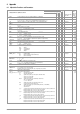
Function-Specific Commands and Device Settings
SSEt txt Set a message signal (sequence / analog interface) X X X X X oFF p. 31
txt: oFF, on (message signal off/on) p. 72
StoP
n Stop address for the sequence X X 11 p. 33
n: 11; ... ; 255
Strt
n Start address for the sequence X X 11 p. 32
n: 11; ... ; 255
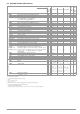
StART_STOP
n1, n2 n: 11; ... ; 255 X X X 11; 11 p. 72
STORE
n, v1, v2, v3, txt Direct transfer of parameter data to memory X X no effect p. 73
n: 11; 12; ... ; 253; 254; 255, memory address
v1:
Voltage setpoint
v2:
Current setpoint
v3:
Memory location-specific dwell time
txt: Switching function, ON or OFF signal level, CLR: complete deletion of memory location data
tdEF
v Dwell time independent of memory location (sequence) X X X X 0.01 s p. 32
v: 00.01; ... , 99.99 (in seconds) p. 74
trG
txt Function selection for the trigger input (analog interface) X unchanged p. 28
T_MODE
txt txt: oFF (trigger input deactivated) X X p. 74
out (trigger input influences the OUTPUT)
rcL (memory recall, step-by-step)
SEq (sequence execution control)
LLO (control panel disabling control)
UI
(Min-Max measured value storage control) remote: “MIN”
tSEt
v Memory location-specific dwell time (sequence) X X X X X tdef p. 31
v: 00.00; 00.01; ... , 99.99 (in seconds), at 00.00: value from tdEF automatically p. 74
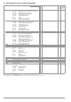
UI
txt Min-Max storage for measured U and I values (setup) X X oFF p. 27
MINMAX
txt txt:
oFF; on; rSt
(Min-Max value storage off/on/reset) X X X p. 68
ULIM
v Voltage setting limit (setup) 0 v U
nom
XXXX U
nom
p. 25
v: 15.0 (example: 15.0 V) p. 75
USET
v Voltage setpoint 0 v ULIM X X X X X 0.000 p. 20
v: 12.5 (example: 12.5 V) p. 76
WAIT
v Additional waiting time XX p. 76
v: 0.001;0.002 ... 9,999 (waiting time in seconds)
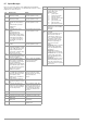
General Commands and Settings
*CLS Clear status command X X no effect p. 61
DCL
, SDC Clear input and output buffers, all settings and register contents unchanged X X no effect p. 65
*DDT txt Define device trigger X X DDT memory p. 61
txt: max. 80 characters, example: *DDT USET 10/ISET 3/OUT ON
2)
cleared
ERAE
n Device dependent event register A enable command X X no effect p. 66
ERBE
n Device dependent event register B enable command X X no effect p. 66
*ESE n Standard event enable command X X no effect p. 66
IFC INTERFACE CLEAR: Rest and initialize the IEC bus interface
(all settings and register contents remain unchanged)
XX
p. 66
*OPC Operation complete command X X no effect p. 62
*PRE n Parallel poll enable register command X X no effect p. 66
*PSC n Power-on status clear command X X no effect p. 62
*RCL n Recall and set X X X no effect p. 62
n: 1 ... 10 a stored device setting
11 ... 255 stored parameters: USET, ISET TSET and SSET
*RST Reset device to default settings X X X p. 63
*SAV nn:0 *SAV 0 deletes the contents of memory locations n1 to n2 by using the address
parameters of the sequence function defined by START_STOP
n1, n2.
XXX
no effect p. 63
1 ... 10 Save current device settings
11 ... 253 Save momentary settings for USET, ISET TSET and SSET
254, 255 Reference values USET and ISET
*SRE n Service request enable command X X no effect p. 66
SRQ Service request X no effect p. 71
*TRG Trigger: trigger the function specified with *DDT X X no effect p. 64
*WAI Wait to continue command X X no effect p. 64
Setting saved with *SAV n:
Default setting after
RESET *RST:
Expla-
nation in
Chapter
on Page
Manual setting or via interface
n=1...10
n=11...255
Setting Command Significance / Effect
Manual
IEEE 488
RS 232C