
User manual


GMC-I Messtechnik GmbH 57
5.11 Varying the Internal Output Resistance Value
Functions
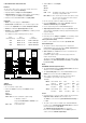
In the voltage regulating mode, internal output resistance has a
value of close to 0 .
The internal output resistance value can be increased for
certain applications, for example simulation of long output cables
or weak automotive batteries.
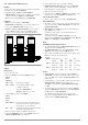
The selected (open-circuit) output voltage is reduced in
proportion to increasing load (Figure 5.11 a).
Figure 5.11 a Dependence of Output Voltage
on Load
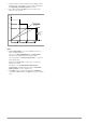
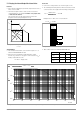
Standardization
The standard characteristic curve shown in Figure 5.11 c is
valid for all KONSTANTER models.
Quick and easy determination indicating which output
resistance R
i
correlates to any given control resistance R
ext
is
made possible with the curve.
R
i
= R
imax
display value
Connection
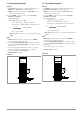
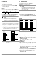
Connect the analog interface as shown in Figure 5.11 b.
The following relationship between internal resistance R
i
and
control resistance R
ext
applies with this wiring configuration:
Example: U
nom
= 40 V, I
nom
= 6 A, R
i
is 0.5
===> R
ext
= 376 k
Figure 5.11 b Wiring for Varying Internal Resistance
Table of R
imax
Values for All KONSTANTER Models
Figure 5.11 c Standardized Curve for Determining Internal Output Resistance for a Specified Control Resistance
U
nom
I
nom
U/V
I / A
ISET
USET
0
R
L
R
L
R
i
m
a
x
R
e
x
t
=
0
R
i
m
i
n
R
e
x
t
R
e
x
t
Device Type 120-20 120-40 120-80
R
imax
/ 2.46 8.2 32.8
Device Type 240-20 240-40 240-80
R
imax
/ 1.23 4.1 16.4
R
ext
=
30 k U
nom
R
i
I
nom
24.4 k
SSP KONSTANTER
+ SENSE
OUT
OUT
SENSE
Analog Interface
SIG1 OUT
SIG2 OUT
TRG IN
TRG IN
+15 V
AGND
Uset
Uset +
Iset +
U-MON
I-MON
+ OUT
+ OUT
R
ext
Output
Settings
USET = Uset
ISET = Iset
Output on / off
R
load
R
imax
R
i
R
ext
/W
10
10
2
10
3
10
4
10
5
10
6
10
7
10
8
10
-4
10
-3
10
-2
10
-1
1
R
imax
= 1.23
U
nom
I
nom
R
imax
24.4 k
R
ext
+24.4 k
R
i
=
;