
User manual


GMC-I Messtechnik GmbH 53
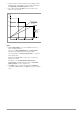
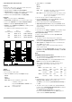
This procedure is continued until load current triggers current
regulating at the output with the lowest voltage setting when
the setpoint value for cumulative current is reached.
This output maintains constant load current until the load
resistor is short-circuited.
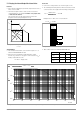
Figure 5.9.1 b U/I Diagram for Direct Parallel Connection
Notes:
Slightly varying voltages occur at the individual outputs as a
result of setting tolerances.
In the event of larger voltage differences, an electronic sink is
activated at the outputs with lower voltage settings.
The sink attempts – in some cases in pulse mode – to reach the
lower voltage value.
Neither the KONSTANTERs nor the power consumer are
damaged as a result.
If problems occur with measurement of load current, the
KONSTANTERs should be linked by means of master-slave
parallel connection (see also chapter 5.9.2).
The outputs can be activated and deactivated commonly by
connecting the SIG1 outputs to the TRG inputs (see also chapter
5.9.2).
Ideal working
current
Ideal working range
for voltage regulation
at the load
U
out1
U
out2
U
out3
I
out1
I
out2
I
out3
R
L
R
L
U
A
/ V
I
A
/ A
range for
regulation at
the load