
User manual


52 GMC-I Messtechnik GmbH
5.8 Trigger Input
Functions
The TRG IN floating optocoupler input allows for remote control of a
device function using a binary signal.
The function to be controlled is selected with the T-MODE
setting (in the trG display).
☞ A detailed description is included on page 28 and page 74.
Connection
Connect the control signal between TRG IN+ and TRG IN-. Refer
to the table below for the respective signal level.
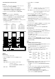
The TRIGGER input can be driven with the +15 V output at the
analog interface via any desired switch (Figure 5.8).
Warning!
The TRG IN trigger input is a floating input and is
functionally isolated from the output current circuit.
This functional isolation is not equivalent to “safety
separation” as specified in electrical safety regulations.
Note
The trigger input is scanned roughly every 10 ms by the digital
control unit. After a signal change has been detected, repeated
querying ensues at short time intervals (suppression of switch
bouncing and interference pulses). This means that:
– Trigger signal pulses must have a minimum duration of
14 ms in order to assure reliable recognition.
– A delay of 1 to 15 ms may occur between application of the
control signal and triggering of the controlled function.
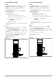
Figure 5.8 Controlling the Trigger Input with a Switching Element /
External Signal
5.9 Parallel Connection
If output current from a single KONSTANTER is insufficient for the
respective application, the outputs of any number of
KONSTANTERs can be parallel connected.
Attention!
!
If outputs with different nominal voltages are parallel
connected, all outputs must be limited to the lowest
utilized nominal voltage value. The ULIM parameter is
used to select this setting.
5.9.1 Direct Parallel Connection
Functions
Easiest way to provide the power consumer with more current
than is available from a single KONSTANTER
KONSTANTERs with differing nominal output voltages can be
used. However, all voltage setpoints must be set or limited to the
same value.
Less suitable for constant voltage regulating mode
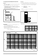
Connection
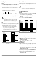
Figure 5.9.1 a Wiring for Direct Parallel Connection
Settings
Deactivate all outputs.
Adjust voltage setpoint USET of all parallel connected
KONSTANTERs to approximately the same value:
Uset = USET1 = USET2 = USET3 = USETn
Adjust current setpoints ISET such that they add up to the desired
cumulative current value Iset:
Iset = ISET1 + ISET2 + ISET3 + ... + ISETn
Activate the outputs.
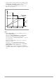
Functional Principle
After switching the outputs on, load current is initially supplied
by the KONSTANTER with the highest voltage setting.
If load resistance is continuously reduced, load current is
continuously increased.
When load current reaches the ISET value selected for the output
which is momentarily supplying power to the consumer, current
limiting is activated for this output.
If load resistance is further decreased, current regulation reduces
output voltage until the voltage value of the output with the next
lowest setting is reached.
As of this point in time, this KONSTANTER also supplies a
portion of the load current.
Output Signal U
s
I
s
OFF High 4 ... 26 V DC (U
s
2 V) / 1.5 k
ON Low 0 ... 1 V DC 0 mA
+ SENSE
OUT
OUT
SENSE
Analog Interface
SIG1 OUT
SIG2 OUT
TRG IN
TRG IN
+15 V
AGND
Uset
Uset +
Iset +
U-MON
I-MON
+ OUT
+ OUT
Output
SSP KONSTANTER
SSP KONSTANTER
+ SENSE
OUT
OUT
SENSE
Analog Interface
SIG1 OUT
SIG2 OUT
TRG IN
TRG IN
+15 V
AGND
Uset
Uset +
Iset +
U-MON
I-MON
+ OUT
+ OUT
Output
Settings
USET = Uset
ISET = Iset
T_MODE OFF
Settings
USET = Uset
ISET = Iset
T_MODE OFF
Uout
Load
Uout
Iout
Load
Iout
I
s
U
s
I
s
approx. 10 mA
+ SENSE
OUT
OUT
SENSE
Analog Interface
SIG1 OUT
SIG2 OUT
TRG IN
TRG IN
+15 V
AGND
Uset
Uset +
Iset +
U-MON
I-MON
+ OUT
+ OUT
Output
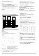
Settings
USET = Uset
ISET1+2+3 = Iset
OUTPUT on/off
+ SENSE
OUT
OUT
SENSE
Analog Interface
SIG1 OUT
SIG2 OUT
TRG IN
TRG IN
+15 V
AGND
Uset
Uset +
Iset +
U-MON
I-MON
+ OUT
+ OUT
Output
Settings
USET = Uset
ISET1+2+3 = Iset
OUTPUT on/off
+ SENSE
OUT
OUT
SENSE
Analog Interface
SIG1 OUT
SIG2 OUT
TRG IN
TRG IN
+15 V
AGND
Uset
Uset +
Iset +
U-MON
I-MON
+ OUT
+ OUT
Output
Settings
USET = Uset
ISET1+2+3 = Iset
OUTPUT on/off
Load
= Only required for sensing mode operation
SSP KONSTANTER
SSP KONSTANTER
SSP KONSTANTER