
User manual


GMC-I Messtechnik GmbH 51
5.6 Voltage Monitoring Output
Functions
The U-MON terminal reads out a voltage U
MU
with reference to
AGND, which is proportional to output voltage Uout.
U-MON serves as a control voltage for master-slave series
connection (see chapter 5.10.2).
However, U-MON can also be used for external measuring,
monitoring and recording.
The following applies:
U
MU
= Uout k
MU
k
Be
l
= 0 ... 10 V
k
MU
= 10 V / Uout
nom
, U-Monitor coefficient
R
i (U-MONITOR)
= 9.8 kU-Monitor internal resistance
R
load
= load resistance
Max. error for U
MU
: 5 mV 1% of actual value (where R
load
>
10 M)
Notes:
U-MON is not a floating output: Its reference point, AGND, is
connected to the negative output pole.
Connecting grounded measuring circuits to the monitor output
may result in erroneous measurements due to leakage current or
ground loops.
The voltage monitoring output makes reference to output
voltage acquired at the sensing leads (see chapter 5.2).
The monitor output is short-circuit proof.
Internal resistance is 9.8 k.
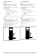
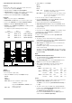
Connection
Figure 5.6 Voltage Monitor Wiring
5.7 Current Monitoring Output
Functions
The I-MON terminal reads out a voltage U
MI
with reference to
AGND, which is proportional to output current Iout.
I-MON serves as a control voltage for master-slave parallel
connection (see chapter 5.9.2).
However, I-MON can also be used for external measuring,
monitoring and recording.
The following applies:
U
MI
= Iout k
MI
k
load
= 0 ... 10 V
k
MI
= 10 V / Iout
nom
, I-Monitor coefficient
R
i (I-MONITOR)
= 9.4 kI-Monitor internal resistance
R
load
= load resistance
Max. error for U
MI
: 5 mV 1% of actual value (where R
load
>
10 M)
Notes:
I-MON is not a floating output: Its reference point, AGND, is
connected to the negative output pole.
Connecting grounded measuring circuits to the monitor output
may result in erroneous measurements due to leakage current or
ground loops.
The monitor output is short-circuit proof.
Internal resistance is 9.4 k.
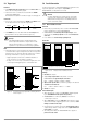
Connection
Figure 5.7 Current Monitor Wiring
k
load
=
R
load
R
load
+ 9.8 k
, load coefficient
+ SENSE
+ OUT
-OUT
-SENSE
Analog Interface
SIG1 OUT
SIG2 OUT
TRG IN
TRG IN +
+15 V
AGND
Uset -
Uset +
Iset +
U-MON
I-MON
Uout
Load
Iout
Settings
USET = Uset
ISET = Iset
OUTPUT on/off
-OUT
+ OUT
V
U
MU
+
OUTPUT
R
load
SSP KONSTANTER
k
load
=
R
i
R
i
+ 9.4 k
, load coefficient
+ SENSE
+ OUT
-OUT
-SENSE
Analog Interface
SIG1 OUT
SIG2 OUT
TRG IN
TRG IN +
+15 V
AGND
Uset -
Uset +
Iset +
U-MON
I-MON
Settings
USET = Uset
ISET = Iset
OUTPUT on/off
-OUT
+ OUT
Uout
Load
Iout
V
R
load
U
MI
+
OUTPUT
SSP KONSTANTER