
User manual


50 GMC-I Messtechnik GmbH
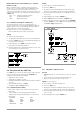
5.4 Regulating Output Voltage
Functions
Output voltage Uout can be set by means of an external control
voltage U
su
via control inputs Uset+ (non-inverting) and Uset
(inverting).
The following applies in the constant voltage regulating mode:
Uout = USET + U
su
k
su
USET = selected voltage setpoint
k
su
= voltage control coefficient = Uout
nom
/ 5 V
Max. adjusting error: 0.05% v. U
nom
2% of the setting value
The voltage control input functions as a differential voltage
input:
Uset+ = non-inverting input:
U
su
= 0 ... + 5 V for Uout = 0 V ... Uout
nom
input resistance: 10 k
Uset = inverting input:
U
su
= 0 ... 5 V for Uout = 0 V ... Uout
nom
,
input resistance: 15 k
Notes:
The control inputs are not floating inputs: Their reference point,
AGND, is connected to the negative pole of the power output.
Connecting grounded circuits to the control input may result in
erroneous settings due to leakage current or ground loops.
If the reference point of control voltage U
su
is connected to the
negative output pole at the load side, the inverting input must
be connected to this point (connection b in Figure 5.4).
Influences resulting form voltage drops in the output lead are
thus avoided.
If control voltage is isolated from the output, connect Uset to
AGND (connection a in Figure 5.4).
If remote adjustment of output voltage is to be accomplished by
means of a potentiometer, wiring can be laid out as shown in
Figure 5.4.
U
su
can be applied as an alternating voltage, for example in order
to superimpose the selected direct voltage USET with
interference signals.
The cut-off frequency of the modulated output voltage depends
upon voltage amplitude.
To a great extent, cut-off frequency remains independent of
the magnitude of the load and selected current limiting thanks
to a special circuit design.
Connection
Figure 5.4 Wiring for Controlling Output Voltage with External
Voltage / External Potentiometer
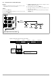
5.5 Regulating Output Current
Functions
Output current Iout can be set with an external voltage U
si
via
the control input Iset+.
The following applies in the constant current regulating mode:
Iout = ISET + U
si
k
si
ISET = selected current setpoint
k
si
= current control coefficient= Iout
nom
/ 5 V
Max. adjusting error: 0.1% of I
nom
2% of setting value
Current control input
Iset + = non-inverting input:
U
si
= 0 ... + 5 V for Iout = 0 A ... Iout
nom
Input resistance is 10 k.
Notes:
The control input is not a floating input: Its reference point, AGND,
is connected to the negative pole of the power output.
Connecting grounded circuits to the control input may result in
erroneous settings due to leakage current or ground loops.
Control voltage U
si
may not be connected to the negative output
pole at the load side. (Figure 5.5)
If remote adjustment of output current is to be accomplished by
means of a potentiometer, wiring can be laid out as shown in
Figure 5.5.
U
si
can be applied as an alternating voltage, for example in order
to superimpose the selected direct current ISET with
interference signals.
The cut-off frequency of the modulated output current depends
upon the voltage amplitude which results from load.
Attention!
!
Control inputs Uset+, Uset– and Iset+ should only be
connected with shielded cable.
Connect the shield to the AGND reference point.
Connection
Figure 5.5 Wiring for Controlling Output Current with External Voltage /
External Potentiometer
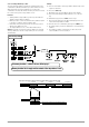
+ SENSE
OUT
OUT
SENSE
Analog Interface
SIG1 OUT
SIG2 OUT
TRG IN
TRG IN
+15 V
AGND
Uset
Uset +
Iset +
U-MON
I-MON
+ OUT
+ OUT
Output
Settings
USET = 0
ISET = Iset
OUTPUT on/off
+ SENSE
OUT
OUT
SENSE
Analog Interface
SIG1 OUT
SIG2 OUT
TRG IN
TRG IN
+15 V
AGND
Uset
Uset +
Iset +
U-MON
I-MON
+ OUT
+ OUT
Output
Settings
USET = 0
ISET = Iset
OUTPUT on/off
Load
Uout
Iout
Uout
Load
a)
Iout
Isu
b)
REF 02
IN
OUT
+5V
2k
Usu
SSP KONSTANTER
SSP KONSTANTER
USET+
USET–
AGND
ISET+
AGND
+ SENSE
OUT
OUT
SENSE
Analog Interface
SIG1 OUT
SIG2 OUT
TRG IN
TRG IN
+15 V
AGND
Uset
Uset +
Iset +
U-MON
I-MON
+ OUT
+ OUT
Output
Settings
USET = Uset
ISET = 0
OUTPUT on/off
+ SENSE
OUT
OUT
SENSE
Analog Interface
SIG1 OUT
SIG2 OUT
TRG IN
TRG IN
+15 V
AGND
Uset
Uset +
Iset +
U-MON
I-MON
+ OUT
+ OUT
Output
Settings
USET = Uset
ISET = 0
OUTPUT on/off
Uout
Load
Uout
I
si
Iout
Usi
REF 02
IN
OUT
+5V
2k
Load
Iout
SSP KONSTANTER
SSP KONSTANTER