
User manual


GMC-I Messtechnik GmbH 49
5.2 Auto-Sensing Mode
In order to be able to take advantage of highly constant output
voltage at the power consumer even if long leads are used,
sensing leads can be used to compensate for voltage drops
within the output leads.
Functions
Sensing lead terminals +SENSE and –SENSE
Acquirement of output voltage, which decisively influences the
voltage measuring and control circuits, directly at the power
consumer (instead of at the output terminals).
Sensing mode operation (remote sensing) offers the following
advantages:
- In the constant voltage regulating mode, current related voltage
drops occurring in the output leads have practically no effect on
voltage supplied to the power consumer.
- Voltage at the output terminals is automatically increased to
compensate for voltage drops.
- In the constant current regulating mode, voltage limiting at the
consumer is independent of output current.
- The voltage value read out by the measuring function
indicates voltage acquired at the sensing leads. Load parameters
such as power consumption and load resistance can thus be
determined more accurately.
The parameters and limit values included in figure in figure 5.2
and in the section entitled Electrical Data apply for operation
with the sensing leads.
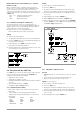
Figure 5.2 Connecting the Power Consumer for
Sensing Mode Operation
C
s+
, C
s-
10 F ... 220 F
U
s+
,U
s-
1 V
I
s+
U
s+
/ 81
I
s-
U
s-
/ 81
Connection
The +SENSE and –SENSE sensing leads from the output
connector plug at the rear panel should be connected as close
as possible to the power consumer.
Connect each respective sensing lead to the appropriate output
pole (+SENSE: +, –SENSE: –).
Interference can be minimized by:
- Twisting the sensing leads and/or
- Shielding the sensing leads (connect shield to ground, the
housing or the negative output pole)
Long output and sensing lead impedances may result in control
fluctuations at the output.
This problem is of course worsened by capacitive consumers.
Control fluctuations can be counteracted with one capacitor
each (C
s+
, C
s-
) between the SENSE and output terminals (see
Figure 5.2).
If the output leads are twisted, their impedance can be reduced
as well.
Incorrect connection of the sensing leads does not damage the
KONSTANTER, although it results in the following reversible events:
- Polarity reversal at sensing leads or interrupted output lead
If output voltage is not being limited at the KONSTANTER by
means of current regulation, it climbs to well above the
selected value.
This condition immediately triggers overvoltage protection
and deactivates the output.
- Interruption of a sensing lead
Automatic reset to local sensing for the respective output
pole.
If the sensing leads have been connected incorrectly,
increasing voltage between the output terminals is not
acquired by the measuring function.
Activation
The remote sensing mode function is activated automatically
after the SENSE terminals have been connected to the power
consumer at the respective output poles.
The function is deactivated by once again interrupting this
connection.
5.3 Status Signal Outputs
Functions
The KONSTANTER is equipped with two open collector
outputs with reference to AGND for reading out status signals,
namely SIG1OUT and SIG2OUT.
The device status or event to be signaled is independent for
both signal outputs.
Selection is made by setting the SIG1 and SIG2 functions.
A detailed description is included on page 29 for manual
operation, and on page 71 for programming.
As a status signal for monitoring devices
For controlling external output relays
Applications
Triggering of certain device functions can be synchronized by
means of connection to the trigger inputs of other
KONSTANTERs (see also chapter 5.9.2).
Connection
Values for connection:
Max. switching voltage: 30 V DC
Max. switching current: 20 mA
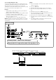
If you want to use the signal outputs to send status signals to
external monitoring devices, pull-up resistors must be used in
order to generate appropriate levels.
The status signal outputs can be connected to the +15 V
terminal with pull-up resistors (at least 1 k), in order to
generate an active high signal of +15 V.
SSP KONSTANTER
Settings
USET = Uset
ISET = Iset
+ SENSE
OUT
OUT
SENSE
Analog Interface
SIG1 OUT
SIG2 OUT
TRG IN
TRG IN
+15 V
AGND
Uset
Uset +
Iset +
U-MON
I-MON
+ OUT
+ OUT
Uout
Load
Iout
Output
R
PU
OUTPUT ON
+5 V
Usig
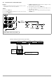
Figure 5.3
Wiring Examples for
Status Signal Outputs