
User manual


48 GMC-I Messtechnik GmbH
5 Analog Interface
5.1 Connector Pin Assignments
SIG1 OUT, SIG2 OUT (output)
Digital status signal outputs with reference to AGND
SIG1 OUT indicates the status defined by SIG1 txt.
SIG2 OUT indicates the status defined by SIG2 txt.
Signal type Open collector
Max. switching voltage 30 V DC
Max. switching current 20 mA
☞ For a detailed description refer to chapter 5.3.
TRG IN+, TRG IN- (input)
Floating, digital control input for controlling a device function
assigned with trG txt.
Low signal: – 26 V U
s
1 V
High signal: 4 V U
s
26 V,
I
s
= (U
s
– 2 V) / 1.5 k
☞ For a detailed description refer to chapter 5.8.
+15 V (output)
This auxiliary voltage output (15 to 17 V DC with reference to
AGND) can be used to control the trigger input, or to supply
power to external components (e.g. reference element for
generating control voltages).
The output is equipped with electronic current limiting to
approximately 60 mA, and is short-circuit proof to AGND.
AGND (analog ground = reference point)
Reference point for analogue control inputs and outputs.
This terminal is internally connected to the minus pole of the
power output via an auto-reversible fuse with a rating of
110 mA.
Uset-, Uset+ (input)
Analog (differential) voltage input with reference to AGND for
controlling output voltage. The following applies when the
output is activated:
Uout = USET + U
su
k
u
Uout = Output voltage in constant voltage regulating mode
USET = Voltage setpoint selected in manual mode
U
su
= External control voltage (0 to 5 V 0 ... Uout
nom
)
k
u
= Control coefficient = Uout
nom
/ 5 V
R
su
= Input resistance (Uset +: 10 k)
Uset–: 15 k
☞ For a detailed description refer to chapter 5.4.
Iset+ (input)
Analog voltage input with reference to AGND for controlling
output current. The following applies when the output is
activated:
Iout = ISET + U
si
k
i
Iout = Output current in constant current regulating mode
ISET = Current setpoint selected in manual mode
U
si
= External control voltage (0 to 5 V 0 ... Iout
nom
)
k
i
= Control coefficient = Iout
nom
/ 5 V
R
si
= Input resistance: 10 k
☞ For a detailed description refer to chapter 5.5.
U-MON (output)
Analog voltage output signal, proportional to output voltage
Uout acquired by the sensing leads.
(0 ... 10 V 0 ... Uout
nom
).
The short-circuit proof output is referenced to AGND, has an
internal resistance of 9.8 k and is short-circuit proof.
☞ For a detailed description refer to chapter 5.6.
I-MON (output)
Analog voltage output signal, proportional to output current
(0 to 10 V 0 ... Iout
nom
).
The short-circuit proof output is referenced to AGND, has an
internal resistance of 9.4 k and is short-circuit proof.
☞ See detailed description in chapter 5.7.
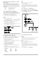
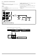
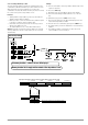
Figure 5.1 Internal Wiring of Analog Interface and Output
(simplified representation)
SIG1 OUT
SIG2 OUT
TRG IN -
TRG IN +
+15 V
AGND
Uset -
Uset +
Iset +
U MON
I MON
SENSE
OUT
OUT
+ SENSE
20
OUT
IN
ADJ
1.5 k
10 k
10 k
10 k
+
9k8
9k4
T
110 mA
+ OUT
+ OUT
+
-
+
-
81
81
120 k
120 k
R
a
R
b
+18 V
U-Reg.
I-Reg.
U-Reg.
I-Reg.
R
a
= R
b
= 60 k for 20 V types
30 k for 40 V types
15 k for 80 V types
ANALOG INTERFACE
OUTPUT
5 k
P
Controlled
37.5 k for 32 V type