
User manual


40 GMC-I Messtechnik GmbH
SbIt – Selecting the Number of Stop Bits
• Either 1 or 2 stop bits can be used.
! Settings at the SSP KONSTANTER and the controller must be
identical.
Settings
☞
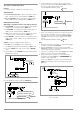
Procedure for selecting Sbit and setting the desired parameter
(see chapter 4.7):
! Sbit appears in the buS display along with the related
parameter (number of stop bits).
Figure 4.7.4 e Path to Selection of the SbIt Text Parameter
4.8 Settings with the <SELECT> Key
The <SELECT> key is located on the front panel next to the
<FUNCTION> key. Depending upon settings in the FUNCTION menu,
it makes 3 different functions available:
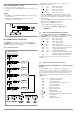
4.8.1 In the Basic Function
Figure 4.8.1 Setting Basic Functions with the SELECT Key
Switching the 7-segment display from Uout and Iout to the
following measured values:
Pout xxx.x Max. output power
U_ xx.xx Min. output voltage
U
xx.xx Max. output voltage
I_ x.xxx Min. output current
I
x.xxx Max. output current
• When the <SELECT> key is pressed the first time, the last
selected parameter name appears at the left-hand display,
and the respective parameter values appears at the right-
hand display.
• When the <SELECT> key is pressed again, the next parameter
name with value is displayed, and so forth.
• Display with the <SELECT> key is exited:
☞ By slightly turning rotary knob [5] or [8].
☞ By pressing the <CE/LOCAL>, <SAVE>, <RCL> or
<FUNCTION> key.
4.8.2 During a Sequence Run and with Step-by-Step Control
The LOCKED/SEQ LED blinks when the SEQUENCE function is
active. The SELECT menu is expanded. It doesn’t matter whether
the SEQUENCE function is in the RUN or the HOLD status.
Pout xxx.x Max. output power
U_ xx.xx Min. output voltage
U
xx.xx Max. output voltage
I_ x.xxx Min. output current
I x.xxx Max. output current
rcL xxx
Current address, memory location number
rrEP
xxx
Number of remaining sequence repetitions
USEt xx.xx Programmed voltage value
ISEt x.xxx Programmed current value
tSEt xx.xx Programmed dwell time (tSEt or tdEF)
for current address, no remaining time
SSEt txt
Output level for SSEt switching function
Otherwise, the same functions can be executed as listed in
chapter 4.8.1.
4.8.3 Display of Stored Data Upon Execution of <RCL>
Display of Data Stored to Setup Memory (1 ... 10) Upon Execution
of <RCL>
After executing the <RCL> command, selecting a memory
location (<> or <> key) and pressing the <ENTER> key, the
device is switched to the read-out mode. Values saved to setup
memory blink at the display. The basic settings stored to the
selected memory location can now be browsed by pressing the
<SELECT> key:
Uset Iset Voltage and current setpoints
tSEt Programmed dwell time
SSEt Signal output status
outP Output switching status after power on
Ulim Voltage setting limit
Ilim Current setting limit
OVP
Overvoltage setpoint
OCP
O
vercurrent protection
dLY
Overcurrent delay
UI_ Min-Max value recording
tdEF Dwell time independent of memory location
Strt Start address
StoP Stop address
rEP Number of repetitions
From the buS function group
*
ENTER
CE/LOCAL FUNCTION
CE/LOCAL
Uout
Iout
FUNCTION
SELECT
SELECT
SELECT
SELECT
SELECT
SAVE
RCL
Uout/IoutUset/Iset
FUNCTION
MENU
SAVE
MENU
RCL
MENU
Abort
Abort
Abort
Abort
Abort