
User manual


GMC-I Messtechnik GmbH 39
! The buS functions menu appears.
☞ Select the Addr function by pressing the <FUNCTION> key, or
the <FUNCTION> and simultaneously the <> key or the <>
key.
! Addr appears at the left-hand display, and the last selected
parameter appears at the right-hand display.
☞ Select an address for the SSP KONSTANTER with the <> or
the <> key.
!
Any address within a range of 0 to 31 may be selected.
! The selected address must be the same as the address
selected for the SSP KONSTANTER at the computer.
! Address 0 is usually assigned to the controller.
! Address 31 means unL (unlist).
☞ Acknowledge your selection with the <ENTER> key.
! The display is returned to the functions menu after
acknowledging with the <ENTER> key.
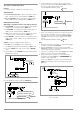
Figure 4.7.4 a Path to Device Address Selection
bAud – Setting Transmission Speed
• Specifies transmission speed in bits per second.
• The baud rate is an operating parameter of the serial interface.
• A low baud rate should be used in the case of large distances
between communicating devices and in EMC-critical
environments.
• Settings at the SSP KONSTANTER and the controller must be
identical.
• The baud rate can be set to one of the following values:
50, 75, 150, 200, 300, 600, 1200, 1800, 2400, 3600, 4800,
7200, 9600 or 19,200 bits per second.
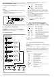
Figure 4.7.4 b Path to Selection of the bAud Text Parameter
Settings
☞
Procedure for selecting bAud and setting the desired parameter
(see chapter 4.7):
! bAud appears in the buS display along with the related
parameter (transmission speed).
dbit – Selecting the Number of Data Bits
• Either 7 or 8 data bits can be used.
• Settings at the SSP KONSTANTER and the controller must be
identical.
Settings
☞
Procedure for selecting dbIt and setting the desired parameter
(see chapter 4.7):
! dbIt appears in the buS display along with the related
parameter (number of data bits).
Figure 4.7.4 c Path to Selection of the dbIt Text Parameter
Pbit – Setting the Parity Bit
• Parity or check bits are used to detect transmission errors.
• They are added to the character string so that the sum of H or
L is even or odd as defined.
• The parity bit can be set to one of the following values:
none No parity bit
ZEro Always 0
EVEn Even numbered
odd Odd numbered
nonE Always 1
! A parity bit should always be used in EMC-critical
environments.
! Settings at the SSP KONSTANTER and the controller must be
identical.
Settings
☞
Procedure for selecting Pbit (see also chapter 4.7):
! Pbit appears in the buS display along with the related
parameter (parity bit).
Figure 4.7.4 d Path to Selection of the PbIt Text Parameter
From the buS function group
Select the
device address
FUNCTION
Press repeatedly if necessary
CE/LOCAL FUNCTION
ENTER
CE/LOCAL
Select the text parameter
from an options loop
From the buS function group
*
ENTER
CE/LOCAL FUNCTION
From the buS function group
*
ENTER
CE/LOCAL FUNCTION
Select the text parameter
from an options loop
From the buS function group
*
ENTER
CE/LOCAL FUNCTION