
User manual


GMC-I Messtechnik GmbH 25
4.7.1 SET – “Setup” Function Group
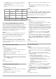
Figure 4.7.1 a Path to Ulim Settings
Ulim – Upper Voltage Setting Limit
Functions
See functions description on page 22.
Settings
The procedure is described in principle in chapter 4.7.
!
The Ulim display appears in the
window for the setup function,
along with a related numeric
parameter [V].
Ilim – Upper Current Setting Limit
Functions
See functions description on page 22.
Settings
The procedure is described in principle in chapter 4.7.
! The Ilim display appears in
the window for the setup
function, along with a
related numeric parameter
[A].
OVP – Overvoltage Protection Trigger Value
Functions
See functions description on page 22.
Settings
The procedure is described in principle in chapter 4.7.
! The OVP display appears in
the window for the setup
function, along with a
related numeric parameter
[V].
☞ The OVP trigger value should be set at least 1 V higher than the
desired USET output voltage in order to prevent undesired
triggering of the OVP function resulting from overshooting due
to sudden output discharging (minimum values: chapter 1.5.3,
“Electrical Data”)!
☞
The
OVP
trigger value makes reference to the prevailing voltage value
between the output terminals of the SSP. This voltage is increased
by the
USET
parameter during sensing mode operation (remote
sensing) by an amount equal to voltage drop at the output leads. For
this reason, the above defined difference between
OVP
and
USET
must be correspondingly increased during sensing mode operation.
☞ The selected parameter becomes immediately active!
Note
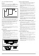
• Overvoltage protection response time is less than 200 μs.
Output voltage generated by the device may exceed OVSET for
the duration of this response time. Maximum overshooting
can be approximately calculated as follows:
Uout = ISET [A] x 200 [μs] / Cout [μF]
ISET = selected current setpoint
Cout = capacitance of the output capacitor
Subsequent discharging time for the output capacitor
depends upon load, and corresponds to the specified values
for response time at Unom 1 V included in chapter 1.5.3.
• Possible causes for triggering overvoltage protection are listed
in chapter 3 [3], “Control Modes”.
FUNCTION
+
FUNCTION
+
FUNCTION
+
FUNCTION Press once
ENTER
Press repeatedly if necessary
Jump to last
edited setup function
Cursor position
SELECT
Resolution of
numeric parameter
Select a value for
the upper voltage limit
(numeric parameter)
CE/LOCAL
CE/LOCAL
CE/LOCAL
CE/LOCAL
Uout
Iout
*
*
*