
User manual


GMC-I Messtechnik GmbH 23
dLY – Output Off Delay for OCP
Functions
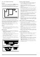
• Delay time prior to deactivation of the power output after
current regulation has been triggered (Iout = Iset)
• Only enabled with activated OCP function (OCP ON)
• If output current Iout drops below Iset before DELAY time
elapses, the shutdown sequence is aborted.
• If current regulation is triggered again, the routine is started
over (at 00.00).
• The default setting after RESET (*RST) is 00.00.
Settings
See description on page 26.
4.6 Display of Momentary Output Values Uout, Iout
and Pout
Uout – Momentary Measured Voltage Value
• Appears at the left-hand display [5].
•The green Uout/V LED [6] lights up and indicates display of the
momentary measured voltage value.
• The measured voltage value is automatically displayed again,
approximately 10 seconds after the last setting has been
made.
• The momentary measured voltage value is displayed
immediately if the user exits the device functions setting mode
by pressing the <CE/LOCAL> key [16].
Iout – Momentary Measured Current Value
• Appears at the right-hand display [8].
• The green Iout/A LED [9] lights up and indicates display of the
momentary measured current value.
• The measured current value is automatically displayed again,
approximately 10 seconds after the last setting has been
made.
• The momentary measured current value is displayed
immediately if the user exits the device functions setting mode
by pressing the <CE/LOCAL> key [16]
Pout – Display Momentary Output Power
Calculated internally based upon momentary measured values
Uout and Iout.
Settings
See description in chapter 4.8.1.
UI_ – Display Measured Values in
U/I Min-Max Memory
Functions
• Reads out stored values for Umin, Umax, Imin and Imax at the
display, or via the computer interface.
• Stored Min-Max values can be read out regardless of the
status selected for the MINMAX function.
Settings
See description in chapter 4.8.1.
4.7 Operating Menu via the FUNCTION Key
The FUNCTION menu consists of the following functions for
configuring the KONSTANTER’s parameters:
Function group Function Parameter (numeric / text)
■ Setup
SEt Ulim NP: xx.xx
Ilim NP: xx.xx
OVP NP: xxx.x
OCP TP: oFF / on
dLY NP: xx.xx
Pon TP: rSt / SbY / rcL
UI
-
TP: oFF / on / rSt
rnd TP: 0 / -1 / -2
■ Analog Interface
AnIF trG TP: oFF / out / rcL / SEq / LLO / UI
-
SiG1 TP: oFF / on / out / Mode / SEq /
SSEt / U-Lo / U-Hi / I-Lo / I-Hi
SiG2 TP: oFF / on / out / Mode / SEq /
SSEt / U-Lo / U-Hi / I-Lo / I-Hi
■ Sequence Function
SEq* tSEt NP: xx.xx
SSEt NP: oFF / on
tdEF NP: xx.xx
Strt NP: xxx (11... 252)
StoP NP: xxx (12... 253)
rEP NP: xxx (cont. or 1 ... 255)
SEq** TP: Go, Strt, StoP, hold, StEP, cont.
* Sequence function: appears at left-hand display, right-hand display is blank.
** Parameter selection for sequence control: appears at left-hand display, selected parameter
appears at right-hand display.
■ Interface Configuration
buS Addr NP: 0 / 1 / ... / 13 /... / 30 / (UNL)
bAUd NP: 50 / 75 / 150 / 200 / ... / 4800 /
9600 / 19200
dbit NP: 7 / 8
Pbit TP: nonE / ZEro / EVEn / odd / onE
Sbit NP: 1 / 2
■ Adjustment (calibration, chapter 7)
CAL dAtE TP: mm.yylast/new adjustment date
CAL TP: Strt
MEAS UoFF
UoFF NP: x.xxxentry of ext. measured value U
MEAS UFS
UFS NP: xx.xxentry of ext. measured value U
MEAS IoFF
IoFF NP: x.xxxentry of ext. measured value I
MEAS IFS
IFS NP: xx.xxentry of ext. measured value I
CAL End
NP: Numeric Parameters
• Can be selected as a specified value or as a value within an
interval with corresponding resolution.
•Adjust resolution (decimal place) by pressing the <SELECT> key.
• Select with the <> key or the <> key.
• Displayed value = selected value.
TP: Text Parameters
• Select parameter with the <> key or the <> key.
• Acknowledge the selected value by pressing the <ENTER> key.