
User manual


22 GMC-I Messtechnik GmbH
If the Pon RCL function is active, the output is automatically
reactivated after the device has returned to its normal
operating temperature.
Functions which may influence the status of the output
include:
4.4
Limiting the Allowable Working Range: Ulim, Ilim
Allowable setting limits for voltage and current can be restricted in
order to assure ideal matching to the working ranges of the
connected power consumer. The Ulim and Ilim setting functions
are provided to this end. Setting options can be selected with the
respective <SELECT> key. Setting resolution is selected with the
<RESOL> key. The setting itself is entered with the scroll keys.
New settings become immediately active.
Attention!
These settings represent so-called soft limits. This means that
values can be selected both manually and via the computer
interface which lie within these limit values, and that a
corresponding error message is otherwise generated.
Attention!
The actual output quantity is the sum of the digitally selected
setpoint value and the setpoint value specified via the analog
interface. This makes it possible to select values which exceed
the specified soft limit.
Ulim – Setting the Upper Voltage Limit Value
Functions
• Upper setting limit (soft limit) for Uset
• Prevents inadvertent violation of the maximum voltage value
when adjusting Uset.
• Protection for the connected power consumer
• Ulim has higher priority than Uset.
• Manual and computer-aided settings for Uset may not exceed
Ulim.
• Ulim cannot be set to a value which is less than a previously
selected Uset value. Uset must be reduced far enough to allow
for the new Ulim setting.
Settings
See description on page 25.
Ilim – Setting the Upper Current Limit Value
Functions
• Upper setting limit (soft limit) for Iset
• Prevents inadvertent violation of the maximum current value
when adjusting Iset.
• Protection for the connected power consumer
• Ilim has higher priority than Iset.
• Manual and computer-aided settings for Iset may not exceed
Ilim.
• Ilim cannot be set to a value which is less than current
setpoint Iset. Iset must be reduced far enough to allow for the
new Ilim setting.
Settings
See description on page 25.
4.5 Description of OVP and OCP Protection Functions
Protection for the connected power consumer and the
KONSTANTER by means of the following functions:
OVP – overvoltage protection
Functions
• Protection for the connected power consumer
• If voltage at the output terminals exceeds the selected OVP
value, the power output is deactivated.
• Triggering of overvoltage protection causes immediate (< 200
s) deactivation of the output (OUTPUT OFF). The HF power
transmitter is disabled, and the electronic sink for discharging
the output capacitors for approximately 350 ms is activated.
In addition, bit 4 (OVPA) is set in event register A. Bit 4 remains
set in status register A for as long as the trigger value is
exceeded.
•The CV LED blinks as soon as overvoltage protection OVP is
triggered (see also chapter 3 [3]), and the red OUTPUT LED
goes out.
• As soon as the shutdown condition no longer exists, the
power output can be reactivated by pressing the <OUTPUT>
key, by transmitting a trigger signal to the analog interface or by
means of computer control (“OUTPUT ON”
➅ red OUTPUT LED
lights up).
Settings
See description on page 25.
OCP – Overcurrent Protection
Functions
• Protects the power consumer from continuous overcurrent.
• Deactivates the power output when load current Iset has been
reached, and the output is switched to the current regulating
mode.
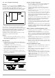
• Current can nevertheless be allowed to exceed Iset for
specified, short periods of time by specifying a delay time (see
below), for example:
! Starting current for electric motors
! In-rush current for capacitive power consumers
! For testing the breaking performance of circuit breakers,
motor protecting switches, fuses etc.
! For determining the short-term load capacity of contacts
and cables, as well as electrical and electronic
components
! In order to maintain short response times when
programming voltage increases
•The CC LED blinks as soon as overvoltage protection OCP is
triggered (see also chapter 3 [3]), and the red OUTPUT LED
goes out.
• The power output can be reactivated at any time by pressing
the <OUTPUT> key, by transmitting a trigger signal to the analog
interface or by means of computer control (OUTPUT ON
➅ red
OUTPUT LED lights up).
Settings
See description on page 26.
Functions Meaning Manual
Operation
Remote
Operation
OVP (OVSEt) Overvoltage
protection
page 25 page 69
OCP Overcurrent
protection
page 26 page 68
Pon
(POWER_ON)
page 26 page 69
SEq Sequence chapter 4.7.4 page 70
trG (T_MODE) page 28 page 74