
User manual

GMC-I Gossen-Metrawatt GmbH 83
8 Appendix
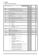
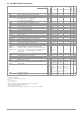
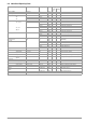
8.1 Adjustable Functions and Parameters
Setting saved with *SAV n:
Default setting after
RESET *RST:
Expla-
nation in
Chapter
on Page
Manual setting or via interface
n=1...10
n=11...255
Setting Command Significance / Effect
Manual
IEEE 488
RS 232C
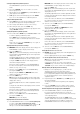
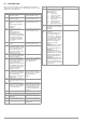
Addr n Set device address for RS 232 or IEEE 488 (interface configuration) X p. 38
ADDRESS nn:0;1; ... ; 31 (device addresses) X unchanged p. 64
bAUd
txt Set transmission speed (interface configuration) X unchanged p. 39
txt: 50; 75; 150; ... ; 4800; 9600; 19.2t (transmission speed in bits per sec.)
CAL Start “CAL” routine in accordance with chapter 7 of the operating instructions X unchanged p. 80
CAL txt, v XX p. 81
dbit
txt Set number of data bits (interface configuration) X unchanged p. 39
txt: 7; 8
dly
v Output off delay for OCP (setup) X X p. 26
DELAY vv:0; 0.1; ... 99.9 (delay time in seconds) X X X 0.00 s p. 65
DISPLAY txt Activate / deactivate digital displays X X ON p. 65
txt: off, on
ILIM v Current setting limit (setup) 0 ≤ v ≤ I
nom
XXXX I
nom
p. 25
v: 12.00 (example: 12.00 A) p. 67
ISET v Current setpoint 0 ≤ v ≤ ILIM X X X X X 0.000 p. 21
v: 10.75 (example: 10.75 A) p. 67
OCP txt Response selection for current limiting (overcurrent protection), (setup) X X X X oFF p. 22
txt: oFF, on (current regulation / output off after expiration of delay time dLY) p. 68
Output (key) Activate / deactivate the output X oFF p. 21
OUTPUT txt txt: OFF, ON XXX p. 69
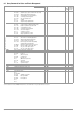
OVP
v Overvoltage protection trigger value (setup) 0 ≤ v ≤ 1.25 x U
nom
X X 1.25 x U
nom
p. 22
OVSET vv:32.5 (example: 32.5 V) X X X p. 69
Pbit
txt Set parity bit (interface configuration) X unchanged p. 39
txt: nonE no parity bit
ZEro always 0
EVEn even numbered
odd odd numbered
onE always 1
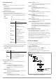
pon
txt Device setting selection after power-up (setup) X p. 26
POWER_ON txt txt: rSt (default settings) X X unchanged p. 69
SbY (last used settings, output deactivated)
rcL (last used settings)
rEP
n Repetition, number of sequence repetitions (sequence) X X cont or 0 = ∞ p. 33
REPETITION nn:1; ... ; 255 XXX p. 70
0
∞
rnd txt Round off the displayed measured value (setup) X unchanged p. 27
txt: 0; –1; –2 (no rounding, round by one or two decimal places)
Sbit
txt Set number of stop bits (interface configuration) X unchanged p. 40
txt: 1; 2
SEq
txt Sequence, automatic memory recall X on
1)
p. 34
SEQUENCE txt txt: Go (start); (off, on (close/end, open)) running SEQ, “stop” p. 70
Hold (pause/suspend); cont (resume); strt, step, stop (step-by-step control) X X
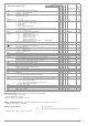
SiG1
txt Signal output 1 (analog interface) X unchanged p. 29
SiG2
txt Signal output 2 (analog interface) X p. 29
Sig1_Sig2 txt1, txt2 txt: oFF SIG inactive (passive high) X X p. 71
on
out
ModE
SEq
SSEt
U_Lo
U_Hi
I_Lo
I_Hi
SIG active (active low)
Signal level depends upon the output’s activation status
OUTPUT on: passive high
OUTPUT OFF: active low
Signal level depends upon momentary control mode
OFF or CV: passive high
CC or OL: active low
Signal level depends upon activated sequence run
Sequence being executed: active low
Signal level depends upon SSET switching function (→ SEQUENCE)
OFF: passive high
ON: active low
Compare measured voltage value with USET from sequence memory location 254.
Measured voltage value ≥ reference value: passive high
Measured voltage value < reference value: active low
Compare measured voltage value with USET from sequence memory location 255.
Measured voltage value ≤ reference value: passive high
Measured voltage value > reference value: active low
Compare measured current value with ISET from sequence memory location 254.
Measured current value ≥ reference value: passive high
Measured current value < reference value: active low
Compare measured current value with ISET from sequence memory location 255.
Measured current value ≤ reference value: passive high
Measured current value > reference value: active low