
User manual

GMC-I Gossen-Metrawatt GmbH 51
5.6 Voltage Monitoring Output
Functions
• The U-MON terminal reads out a voltage U
MU
with reference to
AGND, which is proportional to output voltage Uout.
• U-MON serves as a control voltage for master-slave series
connection (see chapter 5.10.2).
•However, U-MON can also be used for external measuring,
monitoring and recording.
• The following applies:
U
MU
= Uout ⋅ k
MU
⋅ k
Be
l
= 0 ... 10 V
k
MU
= 10 V / Uout
nom
, U-Monitor coefficient
R
i (U-MONITOR)
= 9.8 kΩ, U-Monitor internal resistance
R
load
= load resistance
Max. error for U
MU
: ± 5 mV ± 1% of actual value (where R
load
>
10 MΩ)
Notes:
• U-MON is not a floating output: Its reference point, AGND, is
connected to the negative output pole.
• Connecting grounded measuring circuits to the monitor output
may result in erroneous measurements due to leakage current or
ground loops.
• The voltage monitoring output makes reference to output
voltage acquired at the sensing leads (see chapter 5.2).
• The monitor output is short-circuit proof.
Internal resistance is 9.8 kΩ.
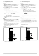
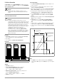
Connection
Figure 5.6 Voltage Monitor Wiring
5.7 Current Monitoring Output
Functions
• The I-MON terminal reads out a voltage U
MI
with reference to
AGND, which is proportional to output current Iout.
• I-MON serves as a control voltage for master-slave parallel
connection (see chapter 5.9.2).
• However, I-MON can also be used for external measuring,
monitoring and recording.
• The following applies:
U
MI
= Iout ⋅ k
MI
⋅ k
load
= 0 ... 10 V
k
MI
= 10 V / Iout
nom
, I-Monitor coefficient
R
i (I-MONITOR)
= 9.4 kΩ; I-Monitor internal resistance
R
load
= load resistance
Max. error for U
MI
: ± 5 mV ± 1% of actual value (where R
load
>
10 MΩ)
Notes:
• I-MON is not a floating output: Its reference point, AGND, is
connected to the negative output pole.
• Connecting grounded measuring circuits to the monitor output
may result in erroneous measurements due to leakage current or
ground loops.
• The monitor output is short-circuit proof.
Internal resistance is 9.4 kΩ.
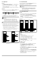
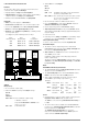
Connection
Figure 5.7 Current Monitor Wiring
k
load
=
R
load
R
load
+ 9.8 kΩ
, load coefficient
+ SENSE
+ OUT
-OUT
-SENSE
Analog Interface
SIG1 OUT
SIG2 OUT
TRG IN +
TRG IN -
+15 V
AGND
Uset -
Uset +
Iset +
U-MON
I-MON
Uout
Load
Iout
Settings
USET = Uset
ISET = Iset
OUTPUT on/off
-OUT
+ OUT
V
U
MU
+
OUTPUT
R
load
SSP KONSTANTER
k
load
=
R
i
R
i
+ 9.4 kΩ
, load coefficient
+ SENSE
+ OUT
-OUT
-SENSE
Analog Interface
SIG1 OUT
SIG2 OUT
TRG IN +
TRG IN -
+15 V
AGND
Uset -
Uset +
Iset +
U-MON
I-MON
Settings
USET = Uset
ISET = Iset
OUTPUT on/off
-OUT
+ OUT
Uout
Load
Iout
V
R
load
U
MI
+
OUTPUT
SSP KONSTANTER