
User manual

50 GMC-I Gossen-Metrawatt GmbH
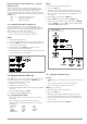
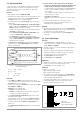
5.4 Regulating Output Voltage
Functions
• Output voltage Uout can be set by means of an external control
voltage U
su
via control inputs Uset+ (non-inverting) and Uset−
(inverting).
• The following applies in the constant voltage regulating mode:
Uout = USET + U
su
⋅ k
su
USET = selected voltage setpoint
k
su
= voltage control coefficient = Uout
nom
/ 5 V
Max. adjusting error: ± 0.05% v. U
nom
± 2% of the setting value
• The voltage control input functions as a differential voltage
input:
Uset+ = non-inverting input:
U
su
= 0 ... + 5 V for Uout = 0 V ... Uout
nom
input resistance: 10 kΩ
Uset− = inverting input:
U
su
= 0 ... − 5 V for Uout = 0 V ... Uout
nom
,
input resistance: 15 kΩ
Notes:
• The control inputs are not floating inputs: Their reference point,
AGND, is connected to the negative pole of the power output.
• Connecting grounded circuits to the control input may result in
erroneous settings due to leakage current or ground loops.
• If the reference point of control voltage U
su
is connected to the
negative output pole at the load side, the inverting input must
be connected to this point (connection b in Figure 5.4).
Influences resulting form voltage drops in the output lead are
thus avoided.
• If control voltage is isolated from the output, connect Uset− to
AGND (connection a in Figure 5.4).
• If remote adjustment of output voltage is to be accomplished by
means of a potentiometer, wiring can be laid out as shown in
Figure 5.4.
• U
su
can be applied as an alternating voltage, for example in order
to superimpose the selected direct voltage USET with
interference signals.
The cut-off frequency of the modulated output voltage depends
upon voltage amplitude.
To a great extent, cut-off frequency remains independent of the
magnitude of the load and selected current limiting thanks to a
special circuit design.
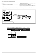
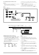
Connection
Figure 5.4 Wiring for Controlling Output Voltage with External
Voltage / External Potentiometer
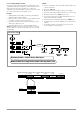
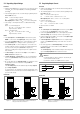
5.5 Regulating Output Current
Functions
• Output current Iout can be set with an external voltage U
si
via
the control input Iset+.
• The following applies in the constant current regulating mode:
Iout = ISET + U
si
⋅ k
si
ISET = selected current setpoint
k
si
= current control coefficient= Iout
nom
/ 5 V
Max. adjusting error: ± 0.1% of I
nom
± 2% of setting value
• Current control input
Iset + = non-inverting input:
U
si
= 0 ... + 5 V for Iout = 0 A ... Iout
nom
• Input resistance is 10 kΩ.
Notes:
• The control input is not a floating input: Its reference point, AGND,
is connected to the negative pole of the power output.
• Connecting grounded circuits to the control input may result in
erroneous settings due to leakage current or ground loops.
• Control voltage U
si
may not be connected to the negative output
pole at the load side. (Figure 5.5)
• If remote adjustment of output current is to be accomplished by
means of a potentiometer, wiring can be laid out as shown in
Figure 5.5.
• U
si
can be applied as an alternating voltage, for example in order
to superimpose the selected direct current ISET with
interference signals.
The cut-off frequency of the modulated output current depends
upon the voltage amplitude which results from load.
Attention!
!
Control inputs Uset+, Uset– and Iset+ should only be
connected with shielded cable.
Connect the shield to the AGND reference point.
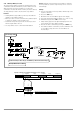
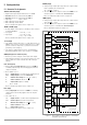
Connection
Figure 5.5 Wiring for Controlling Output Current with External Voltage /
External Potentiometer
+ SENSE
−OUT
−OUT
−SENSE
Analog Interface
SIG1 OUT
SIG2 OUT
TRG IN +
TRG IN −
+15 V
AGND
Uset −
Uset +
Iset +
U-MON
I-MON
+ OUT
+ OUT
Output
Settings
USET = 0
ISET = Iset
OUTPUT on/off
+ SENSE
−OUT
−OUT
−SENSE
Analog Interface
SIG1 OUT
SIG2 OUT
TRG IN +
TRG IN −
+15 V
AGND
Uset −
Uset +
Iset +
U-MON
I-MON
+ OUT
+ OUT
Output
Settings
USET = 0
ISET = Iset
OUTPUT on/off
Load
Uout
Iout
Uout
Load
a)
Iout
Isu
b)
REF 02
IN
OUT
+5V
2k
Usu
SSP KONSTANTER
SSP KONSTANTER
USET+
USET–
AGND
ISET+
AGND
+ SENSE
−OUT
−OUT
−SENSE
Analog Interface
SIG1 OUT
SIG2 OUT
TRG IN +
TRG IN −
+15 V
AGND
Uset −
Uset +
Iset +
U-MON
I-MON
+ OUT
+ OUT
Output
Settings
USET = Uset
ISET = 0
OUTPUT on/off
+ SENSE
−OUT
−OUT
−SENSE
Analog Interface
SIG1 OUT
SIG2 OUT
TRG IN +
TRG IN −
+15 V
AGND
Uset −
Uset +
Iset +
U-MON
I-MON
+ OUT
+ OUT
Output
Settings
USET = Uset
ISET = 0
OUTPUT on/off
Uout
Load
Uout
I
si
Iout
Usi
REF 02
IN
OUT
+5V
2k
Load
Iout
SSP KONSTANTER
SSP KONSTANTER