
User manual

48 GMC-I Gossen-Metrawatt GmbH
5 Analog Interface
5.1 Connector Pin Assignments
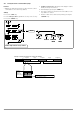
SIG1 OUT, SIG2 OUT (output)
• Digital status signal outputs with reference to AGND
• SIG1 OUT indicates the status defined by SIG1 txt.
• SIG2 OUT indicates the status defined by SIG2 txt.
• Signal type Open collector
• Max. switching voltage 30 V DC
• Max. switching current 20 mA
☞ For a detailed description refer to chapter 5.3.
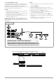
TRG IN+, TRG IN- (input)
• Floating, digital control input for controlling a device function
assigned with trG txt.
• Low signal: – 26 V ≤ U
s
≤+ 1 V
• High signal: + 4 V ≤ U
s
≤+ 26 V,
I
s
= (U
s
– 2 V) / 1.5 kΩ
☞ For a detailed description refer to chapter 5.8.
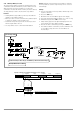
+15 V (output)
• This auxiliary voltage output (15 to 17 V DC with reference to
AGND) can be used to control the trigger input, or to supply
power to external components (e.g. reference element for
generating control voltages).
• The output is equipped with electronic current limiting to
approximately 60 mA, and is short-circuit proof to AGND.
AGND (analog ground = reference point)
• Reference point for analogue control inputs and outputs.
• This terminal is internally connected to the minus pole of the
power output via an auto-reversible fuse with a rating of
110 mA.
Uset-, Uset+ (input)
• Analog (differential) voltage input with reference to AGND for
controlling output voltage. The following applies when the
output is activated:
• Uout = USET + U
su
⋅ k
u
Uout = Output voltage in constant voltage regulating mode
USET = Voltage setpoint selected in manual mode
U
su
= External control voltage (0 to 5 V 0 ... Uout
nom
)
k
u
= Control coefficient = Uout
nom
/ 5 V
R
su
= Input resistance (Uset +: 10 kΩ)
Uset–: 15 kΩ
☞ For a detailed description refer to chapter 5.4.
Iset+ (input)
• Analog voltage input with reference to AGND for controlling
output current. The following applies when the output is
activated:
• Iout = ISET + U
si
⋅ k
i
Iout = Output current in constant current regulating mode
ISET = Current setpoint selected in manual mode
U
si
= External control voltage (0 to 5 V 0 ... Iout
nom
)
k
i
= Control coefficient = Iout
nom
/ 5 V
R
si
= Input resistance: 10 kΩ
☞ For a detailed description refer to chapter 5.5.
U-MON (output)
• Analog voltage output signal, proportional to output voltage
Uout acquired by the sensing leads.
(0 ... 10 V 0 ... Uout
nom
).
• The short-circuit proof output is referenced to AGND, has an
internal resistance of 9.8 kΩ and is short-circuit proof.
☞ For a detailed description refer to chapter 5.6.
I-MON (output)
• Analog voltage output signal, proportional to output current
(0 to 10 V 0 ... Iout
nom
).
• The short-circuit proof output is referenced to AGND, has an
internal resistance of 9.4 kΩ and is short-circuit proof.
☞ See detailed description in chapter 5.7.
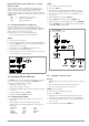
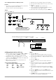
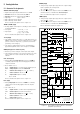
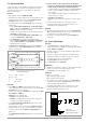
Figure 5.1 Internal Wiring of Analog Interface and Output
(simplified representation)
SIG1 OUT
SIG2 OUT
TRG IN -
TRG IN +
+15 V
AGND
Uset -
Uset +
Iset +
U MON
I MON
− SENSE
− OUT
− OUT
+ SENSE
20
OUT
IN
ADJ
1.5 k
−
+
10 k
10 k
10 k
−
+
9k8
9k4
+T
110 mA
+ OUT
+ OUT
+
−
-
+
-
81
81
120 k
120 k
R
a
R
b
−
+
+18 V
U-Reg.
I-Reg.
U-Reg.
I-Reg.
R
a
= R
b
= 60 k for 20 V types
30 k for 40 V types
15 k for 80 V types
ANALOG INTERFACE
OUTPUT
5 k
μP
Controlled
37.5 k for 32 V type