
User manual

GMC-I Messtechnik GmbH 25
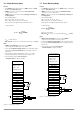
5.10 Varying Internal Output Resistance
Function
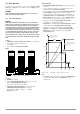
• Internal resistance at the output is equal to practically 0 Ω in the
voltage regulating mode.
• Internal resistance can be increased at the output for some
applications, e.g. for the simulation of long power leads or weak
automotive batteries.
The selected (open-circuit) output voltage drops proportionately
as load increases (see figure 5.10 a).
Figure 5.10 a Output Voltage Relative to Load
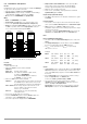
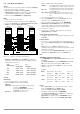
Standardization
• The standardized curve shown in figure 5.10 applies to all
device types.
• It is plain to see from the characteristic curve, which internal
output resistance R
i
results from which control resistance R
ext
.
R
i
= R
imax
⋅ display value
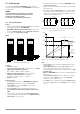
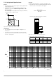
Connection
• Wire the analog interface in accordance with figure 5.10 c.
• When wired as shown, the following relationship of internal
resistance R
i
to control resistance R
ext
applies:
Example: U
nom
= 40 V, I
nom
= 6 A, R
i
is 0.5 Ω
===> R
ext
= 376 kΩ
Figure 5.10 c Wiring for Varying Internal Resistance
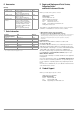
• Tab le of R
imax
Values for all device types
Figure 5.10 b Standardized curve for the determination of internal output resistance based upon a predefined control resistance
U
nom
I
nom
U/V
I/A
ISET
USET
0
R
L
R
L
↑
R
i
m
a
x
@
R
e
x
t
=
0
R
i
m
i
n
@
R
e
x
t
=
∞
R
e
x
t
↑
Device Type 120-20 120-40 120-80
R
imax
/ Ω 2.46 8.2 32.8
Device Type 240-20 240-40 240-80 320-32
R
imax
/ Ω 1.23 4.1 16.4 2.19
R
ext
30 kΩ x U
nom
R
i
x I
nom
------------------------------------ 24.4 kΩ–=
SLP-KONSTANTER
+SENSE
-OUT
-OUT
-SENSE
Analog Interface
SIG1 OUT
SIG2 OUT
TRG IN –
TRG IN +
+ 15 V
AGND
Uset -
Uset +
Iset +
U-MON
I-MON
+OUT
+OUT
R
ext
Output
Settings
USET = Uset
ISET = Iset
Output ON/OFF
R
load
R
imax
R
i
R
ext
/ Ω
10
10
2
10
3
10
4
10
5
10
6
10
7
10
8
10
-4
10
-3
10
-2
10
-1
1