
User manual


24 GMC-I Messtechnik GmbH
5.9.2 Series Master-Slave Operation
Function
Series master-slave connection provides for significant advantages
as opposed to direct series connection:
• Equally suitable for voltage and current regulation
• Output parameters (cumulative output voltage, current limiting,
output ON/OFF) are fully controlled by the master.
• All interconnected KONSTANTERs are equally loaded.
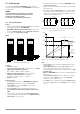
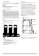
Wiring
• Define one device as the master.
• Connect master and slave devices as shown in figure 5.9.2.
• Connect the power leads to the external points in the series circuit.
• Balance the individual output voltages with R
match
.
Figure 5.9.2 Wiring for Series Master-Slave Operation
• Balancing and optimization can be simplified by combining a
fixed-value resistor (metal film resistor, T
k
≤ 50 ppm / K) and a
trimming resistor for R
match
.
Procedure
Initial Start-Up:
• Do not load the outputs (no-load operation).
• Switch the master on (mains switch) and set:
OUTPUT off
USET = Uset / n Uset: desired cumulative output voltage
n: number of KONSTANTERs
Only valid if nominal values for all devices
are identical, see notes as well
ISET = Iset Desired current limit value
• Switch on Slave 1 (mains switch) and set:
OUTPUT on The output remains inactive at first even though
the OUTPUT key is depressed, because it has
been disabled by the master via the TRG input.
USET = 0 V The USET rotary knob can be deactivated by
setting ULIM to 0 V.
ISET > ISET
master
Current limiting for the slaves must be set at
least 2% higher than it is at the master, e.g. to
max.
• Proceed as described above for all slaves.
• Press the OUTPUT ON key at the master. All slave outputs are
switched on and set simultaneously in this way.
• Check the output voltages displayed at the KONSTANTERs.
• Output voltage for each individual slave can be precisely set to
match output voltage at the master by adjusting R
match
.
Changes appear immediately at the respective display.
• Connect the consumer.
• From now on, (cumulative) output parameters are set and
regulated entirely by the master.
Repeat Start-Ups (after initial start-up):
• The order in which devices are switched off and back on again
is irrelevant.
Functional Principle
• The master controls output voltage at the downstream device
(slave 1) via its voltage control input with the voltage monitoring sig-
nal.
• Slave 1 functions as a master for slave 2 and so forth.
Cumulative output voltage is thus always proportional to output
voltage from the master.
The master controls the OUTPUT ON/OFF status of the slaves via
connection of the master SIG1 output to the slave TRG input.
Notes
KONSTANTERs with Different Nominal Values
• The KONSTANTER with the lowest nominal current must be used as
the master.
• The current setting range for all other KONSTANTERs must be lim-
ited to the lowest nominal value with the ILIM parameter.
• Uout
Slave
is only equivalent to Uout
Master
as a percentage with
reference to U
nom
.
Example:
General
• If the connector leads to the analog interface and the sensing
leads are longer than 1 m, use shielded cable.
Connect the shield to ground / housing or AGND.
• The same current flows through all KONSTANTERs.
The measured current value from the master is thus sufficient for
the measurement of load current.
Voltage values from all interconnected KONSTANTERs must be
added together in order to calculate cumulative output voltage.
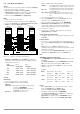
Slave
Nominal Voltage
R
match
Nominal Value
R
match
Combination
20 V 40 kΩ / 0.2 W 36 kΩ +10 kΩ pot.
32 V 64 kΩ / 0.2 W 60 kΩ + 10 kΩ pot.
40 V 80 kΩ / 0.2 W 75 kΩ + 10 kΩ pot.
80 V 160 kΩ / 0.2 W 150 kΩ + 20 kΩ pot.
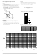
SLP-KONSTANTER
SLP-KONSTANTER
SLP-KONSTANTER
+SENSE
-OUT
-OUT
-SENSE
Analog Interface
SIG1 OUT
SIG2 OUT
TRG IN –
TRG IN +
+ 15 V
AGND
Uset -
Uset +
Iset +
U-MON
I-MON
+OUT
+OUT
Master
Settings
USET = Uset / n
ISET = Iset
OUTPUT ON/OFF
+SENSE
-OUT
-OUT
-SENSE
Analog Interface
SIG1 OUT
SIG2 OUT
TRG IN –
TRG IN +
+ 15 V
AGND
Uset -
Uset +
Iset +
U-MON
I-MON
+OUT
+OUT
Slave 2
Settings
USET = 0 V
ISET > Iset
master
OUTPUT on
Load
R
sym
R
sym
+SENSE
-OUT
-OUT
-SENSE
Analog Interface
SIG1 OUT
SIG2 OUT
TRG IN –
TRG IN +
+ 15 V
AGND
Uset -
Uset +
Iset +
U-MON
I-MON
+OUT
+OUT
Slave 1
Settings
USET = 0 V
ISET > Iset
master
OUTPUT on
Output
Output
Output
= Only required for sensing mode operation
Master: SLP 120-40
U
nom
:
40 V
I
nom
:
6 A
Settings: USET:12 V(30%) ISET:3 A
Slave 1: SLP 120-20 U
nom
:20 V I
nom
: 10 A
Results in: Uout:6 V(30%) Iout:3 A
Slave 2: SLP 120-20 U
nom
:20 V I
nom
: 10 A
Results in: Uout:6 V(30%) Iout: 3 A