
User manual

GMC-I Messtechnik GmbH 13
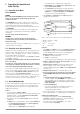
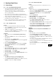
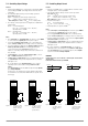
3 Controls, Displays and Connectors
Figure 3.1 Front Panel Controls, Displays and Connectors
[1] Mains Switch <POWER>
For switching the KONSTANTER on and off.
After mains power has been switched on, the KONSTANTER
adjusts itself to all of the values which have been predeter-
mined by manual control settings or signals received at the
analog interface. It is then switched to the standby mode
and is ready for operation.
When the KONSTANTER is switched off, it is disconnected at
both poles from the mains and the output is deactivated.
CAUTION!
Do not switch the device on and off repeatedly at short intervals.
Effectiveness of in-rush current limiting may be impaired in such
cases, which may cause the mains fuse to blow!
[2] Output ON/OFF key <OUTPUT>
The power output is activated and deactivated by
pressing the <OUTPUT> key.
If the output is active, one of the control mode displays lights
up, namely CV or CC [3].
No significant output voltage overshooting occurs during
activation and deactivation of the power output.
When the device is switched off, an electronic sink is acti-
vated for approximately 300 ms, which rapidly discharges
the output capacitors. The output then becomes “highly
resistive” (R
i
> 50 kΩ II 250 μF).
☞ Refer to chapter 4.3 for detailed information.
CAUTION!
The output terminals are not electrically isolated when the output is
deactivated.
[3] Control Mode Displays
The three LEDs indicate the current operating status (control
mode) of the output.
“CV” illuminated Constant voltage mode (Uout = Uset)
“CC” illuminated Constant current mode (Iout = Iset)
“Pmax” illuminated Overload limiting / overtemperature
protection has been triggered.
The output is deactivated as a result.
[4] Left-Hand Display
The measured value for output voltage Uout in volts appears as
the standard display value at the left-hand display.
As long as the <DISPLAY Uset/Iset> key [9] is depressed, the
manually selected voltage setpoint Uset appears at the display.
Type / Nom.Voltage Display Resolution / Range
20 V 0.01 (max. 19.99)
32/40/80 V 0.1 (xx.x)
[5] Right-Hand Display
The measured value for output current Iout in amperes appears
as the standard display value at the right-hand display.
As long as the <DISPLAY Uset/Iset> [9] key is depressed, the
manually selected current setpoint Iset appears at the display.
Display Resolution / Range 0.01 (max. 19.99)
☞ Refer to chapter 4.3 for detailed information.
[6] Front Panel Output
The selected constant voltage or constant current is made
available at the safety jacks at the front panel, or at the
terminals on the rear panel [13].
– (blue) Negative output terminal
+ (red) Positive output terminal
(yellow-green) The output can be grounded here if
desired, or the shield can be con-
nected here if shielded power leads
are used. The ground terminal is con-
nected to the housing and the mains
connection earthing contact.
☞ Refer to chapter 2.2 for detailed information.
123 4 5
101196
87