
User manual


GMC-I Gossen-Metrawatt GmbH 19
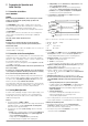
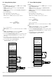
5.4 Controlling Output Voltage
Function
• Output voltage Uout can be controlled via control inputs Uset+
(non-inverting) and Uset− (inverting) with an external control
voltage U
su
.
• The following applies during constant voltage operation:
Uout = USET + U
su
⋅ k
su
USET: manually selected voltage setpoint value
k
su
: voltage control coefficient = Uout
nom
/ 5 V
– Max. setting error: ± 0.05% of U
nom
± 2% of setting value
• The voltage control input has been designed as a differential
voltage input:
Uset+: non-inverting input:
U
su
= 0 ... +5 V for Uout = 0 V ... Uout
nom
,
input impedance: 10 kΩ
Uset−: inverting input:
U
su
= 0 ... −5 V for Uout = 0 V ... Uout
nom
,
input impedance: 15 kΩ
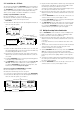
Notes
• The control inputs are not floating inputs, the reference point AGND
is connected to the negative pole of the power output.
• Connecting grounded current circuits to the control input may
lead to erroneous settings due to leakage current or earth loops.
• If control voltage U
su
is applied to the output’s negative pole with its
reference point at the load side, the inverting input must be
connected to this point (connection b in figure 5.4 a).
Influences caused by voltage drops at the load conductor are
thus avoided.
• If control voltage is electrically isolated from the output, connect
Uset− to AGND (connection a in figure 5.4 a).
• If remote control of output voltage is to be accomplished by means
of a potentiometer, wiring can be implemented in accordance
with figure 5.4 b.
• U
su
can be applied as an alternating voltage, e.g. in order to
superimpose the selected direct voltage USET with fault
signals.
The cut-off frequency of the modulated output voltage depends
upon voltage amplitude.
However, the cut-off frequency remains largely independent
of load and the selected current limit thanks to special circuit
technology.
Figure 5.4 a Wiring for control
of output voltage
with an external
voltage
Figure 5.4 b Wiring for control
of output voltage
with an external
potentiometer
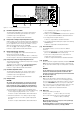
5.5 Controlling Output Current
Function
• Output current Iout can be controlled with an external control
voltage U
si
via the control input Iset+.
• The following applies during constant current operation:
Iout = ISET + U
si
⋅ k
si
ISET: manually selected current setpoint value
k
si
: current control coefficient = Iout
nom
/ 5 V
Max. setting error: ±0.1% v. I
nom
± 2% of setting value
• Current Control Input
Iset+: non-inverting input:
U
si
= 0 ... +5 V for Iout = 0 A ... Iout
nom
,
• Input impedance is equal to 10 kΩ.
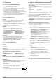
Notes
• The control input is not a floating input, the reference point AGND is
connected to the negative pole of the power output.
• Connecting grounded current circuits to the control input may
lead to erroneous settings due to leakage current or earth loops.
• Control voltage U
si
may not be connected to the input’s negative
pole at the load side (see figure 5.5 a).
• If remote control of output current is to be accomplished by means
of a potentiometer, wiring can be implemented in accordance
with figure 5.5 b.
• U
si
can be applied as an alternating voltage, e.g. in order to
superimpose the selected direct current ISET with fault signals.
The cut-off frequency of the modulated output current depends
upon the load-related voltage amplitude.
CAUTION!
Control inputs Uset +, Uset – and Iset + should only be connected with
shielded cable.
Connect the shield to reference point AGND.
Figure 5.5 a Wiring for control
of output current
with an external
voltage
Figure 5.5 b Wiring for control
of output current
with an external
potentiometer
SLP-KONSTANTER SLP-KONSTANTER
Einstellung
USET = 0
ISET = Isoll
OUTPUT on / off
+SENSE
-OUT
-OUT
-SENSE
Analog Interface
SIG1 OUT
SIG2 OUT
TRG IN +
TRG IN -
+ 15 V
AGND
Uset -
Uset +
Iset +
U-MON
I-MON
+OUT
+OUT
Einstellung
USET = 0
ISET = Isoll
OUTPUT on / off
+SENSE
-OUT
-OUT
-SENSE
Analog Interface
SIG1 OUT
SIG2 OUT
TRG IN +
TRG IN -
+ 15 V
AGND
Uset -
Uset +
Iset +
U-MON
I-MON
+OUT
+OUT
Last
Uout
Iout
Uout
Last
a)
I
out
I
su
b)
REF 02
IN
OUT
+5V
2k
Output
Output
U
su
USET+
USET-
AGND
ISET+
AGND
SLP-KONSTANTER SLP-KONSTANTER
Settings
USET = Uset
ISET = 0
OUTPUT ON/OFF
+SENSE
-OUT
-OUT
-SENSE
Analog Interface
SIG1 OUT
SIG2 OUT
TRG IN +
TRG IN -
+ 15 V
AGND
Uset -
Uset +
Iset +
U-MON
I-MON
+OUT
+OUT
Uout
Load
Settings
USET = Uset
ISET = 0
OUTPUT ON/OFF
Uout
+SENSE
-OUT
-OUT
-SENSE
Analog Interface
SIG1 OUT
SIG2 OUT
TRG IN +
TRG IN -
+ 15 V
AGND
Uset −
Uset +
Iset +
U-MON
I-MON
+OUT
+OUT
I
si
Iout
U
si
REF
02
IN
OUT
+5V
2k
Load
Iout
Output
Output