
User manual


18 GMC-I Gossen-Metrawatt GmbH
5.2 Status Signal Outputs
Function
• The KONSTANTER includes two digital open collector outputs
with reference to AGND for the generation of status signals.
• SIG1 OUT – indicates activation status of the power output
OUTPUT ON = passive high (= OFF)
OUTPUT OFF = active low (= ON)
– If this output is connected to the trigger input of a second
KONSTANTER, the power outputs of both devices can be acti-
vated and deactivated simultaneously (see also chapters
5.8.2 and 5.9.2).
–As a message signal for transmission to monitoring equipment
– For the control of external output relays
Due to the fact that output voltage drops off very quickly
when the output is switched off (< 1 ms), the relay can be
released load-free with resistive consumers.
• SIG2 OUT – indicates the active power output control mode.
– Constant current (CC) or overload (Pmax) = active low (= ON)
– Constant voltage (CV) or OUTPUT OFF = passive high (= OFF)
–As a message signal to monitoring equipment
Connection
• Connected load values
Max. switching voltage 30 V DC
Max. switching current 20 mA
Low level < 1 V at I
s
≤ 20 mA
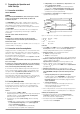
• In order to generate an “active high” signal of + 15 V, the status
signal outputs can be connected to the +15 V terminal with
pull-up resistors R
PU
with a value of at least 1 kΩ.
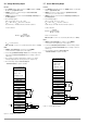
Figure 5.2 Wiring examples for the status signal outputs
5.3 Trigger Input
Function
• The floating optocoupler input “TRG IN” allows for remote control of
a the OUTPUT function with a binary control signal.
• The trigger input is only active as long as the OUTPUT key is
depressed (ON).
• If this input is connected to the signal of a second KONSTANTER,
the power outputs of both devices can be activated and deacti-
vated simultaneously (see also chapters 5.8.2 and 5.9.2).
• The OUTPUT ON/OFF function can be controlled by means of
user-specific signals to the trigger input in automated testing
systems.
Connection
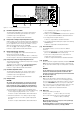
• Connect the control signal between TRG IN + and TRG IN -.
Appropriate signal levels are listed in the following table.
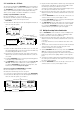
• The TRIGGER can be controlled with the + 15 V output at the
analog interface via any desired switch (see figure 5.3 a).
WARNING
Trigger input TRG IN is a floating input and is functionally isolated from the
output current circuit.
This functional isolation is not to be construed with “protective
separation” as set forth in electrical safety regulations.
Figure 5.3 a Controlling the
trigger input with
a switching element
Figure 5.3 b Controlling the
trigger input with
an external signal
SLP-KONSTANTER
Settings
USET = Uset
ISET = Iset
+SENSE
-OUT
-OUT
-SENSE
Analog Interface
SIG1 OUT
SIG2 OUT
TRG IN +
TRG IN -
+ 15 V
AGND
Uset -
Uset +
Iset +
U-MON
I-MON
+OUT
+OUT
Uout
Load
Iout
Output
R
PU
OUTPUT ON
+5 V
Usig
Signal U
s
I
s
Output
High 4 ... 26 V DC (U
s
− 2 V) / 1.5 kΩ OFF
Low 0 ... 1 V DC 0 mA ON
SLP-KONSTANTER
SLP-KONSTANTER
Settings
USET = Uset
ISET = Iset
+SENSE
-OUT
-OUT
-SENSE
Analog Interface
SIG1 OUT
SIG2 OUT
TRG IN +
TRG IN -
+ 15 V
AGND
Uset -
Uset +
Iset +
U-MON
I-MON
+OUT
+OUT
Uout
Load
Settings
USET = Uset
ISET = Iset
Uout
+SENSE
-OUT
-OUT
-SENSE
Analog Interface
SIG1 OUT
SIG2 OUT
TRG IN +
TRG IN -
+ 15 V
AGND
Uset -
Uset +
Iset +
U-MON
I-MON
+OUT
+OUT
Iout
Load
Iout
Output
Output
I
s
ca. 10 mA
I
s
U
s
OUTPUT ON
OUTPUT ON