
User manual


GMC-I Gossen-Metrawatt GmbH 17
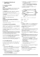
5 Control via the Analog Interface
5.1 Connector Assignments
SIG1 OUT, SIG2 OUT (output)
• Digital status signal outputs with reference to AGND
• SIG1 OUT indicates the status of the power output
• SIG2 OUT indicates the current control mode
• Signal type open collector
• Max. switching voltage 30 V DC
• Max. switching current 20 mA
☞ Refer to chapter 5.2 for detailed information.
TRG IN+, TRG IN- (input)
• Floating digital control input for switching the power output on
and off
• Low signal: –26 V ≤ U
s
≤ +1 V
• High signal: +4 V ≤ U
s
≤ +26 V
I
s
= (U
s
- 2 V) / 1.5 kΩ
☞ Refer to chapter 5.3 for detailed information.
+15 V (output)
• This auxiliary voltage output (14 ... 17.5 V DC with reference to
AGND) can be used to control the trigger input or to supply
external consumers with power (e.g. reference component for
the generation of control voltages).
• The output is equipped with electronic current limiting to
approximately 60 mA, and is short-circuit proof to AGND.
AGND (analog ground = reference point)
• Reference point for analog control inputs and outputs
• This terminal is internally connected to the negative pole of the
power output via an automatic resetting fuse (110 mA rating).
Uset-, Uset+ (input)
• Analog (differential) voltage input with reference to AGND for
controlling output voltage. The following applies when the
output is active:
• Uout = USET + U
su
⋅ k
su
Uout: output voltage during constant voltage operation
USET: manually selected voltage setpoint value
U
su
: external control voltage (0 ... 5 V 0 ... Uout
nom
)
k
su
: voltage control coefficient = Uout
nom
/ 5 V
R
su
: input impedance Uset+: 10 kΩ
Uset–: 15 kΩ
☞ Refer to chapter 5.4 for detailed information.
Iset+ (input)
• Analog voltage input with reference to AGND for controlling output
current. The following applies when the output is active:
• Iout = ISET + U
si
⋅ k
si
Iout: output current during constant current operation
ISET: manually selected current setpoint value
U
si
: external control voltage (0 ... 5 V 0 ... Iout
nom
)
k
si
: current control coefficient = Iout
nom
/ 5 V
R
si
: input impedance: 10 kΩ
☞ Refer to chapter 5.5 for detailed information.
U-MON (output)
• Analog voltage output, proportional to output voltage Uout
which is acquired by the sensing leads
(0 ... 10 V 0 ... Uout
nom
).
• This output, with reference to AGND, has an internal resistance
of 9.8 kΩ and is short-circuit proof.
☞ Refer to chapter 5.6 for detailed information.
I-MON (output)
• Analog voltage output proportional to actual output current Iout
(0 ... 10 V 0 ... Iout
nom
)
• This output, with reference to AGND, has an internal resistance
of 9.4 kΩ and is short-circuit proof.
☞ Refer to chapter 5.7 for detailed information.
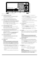
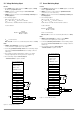
Figure 5.1 Internal connection to the analog interface and
the output (simplified schematic)
SIG1 OUT
SIG2 OUT
TRG IN -
TRG IN +
+ 15 V
AGND
Uset -
Uset +
Iset +
U MON
I MON
− SENSE
− OUT
− OUT
+ SENSE
20
OUT
IN
ADJ
1,5 k
−
+
10 k
10 k
10 k
−
9k8
9k4
+T
110 mA
+ OUT
+ OUT
−
-
+
-
81
81
120k
120k
R
a
R
b
−
+
OUTPUT Status
Control Mode CV/CC
OUTPUT Control
+18 V
U-Reg.
I-Reg.
U-Reg.
I-Reg.
R
a
= R
b
= 60 k for 20 V devices
37.5 k for 32 V devices
30 k for 40 V devices
ANALOG INTERFACE
OUTPUT
5 k
+
+
15 k for 80 V devices