
User manual


14 GMC-I Gossen-Metrawatt GmbH
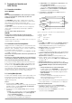
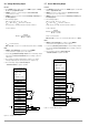
Figure 3.2 Controls and Connectors at the Rear Panel
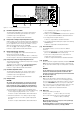
[7] Limit Value Adjustment <Ulim>
The upper limit value Ulim for the voltage setting range is
selected with this trimming potentiometer. Use a size 3
screwdriver only for this adjustment.
☞ Refer to chapter 4.1.2 for detailed information.
[8] Rotary Knob for Voltage Setpoint Adjustment <Uset>
Output voltage can be set with this rotary knob. Adjustment
is accomplished with a ten-turn potentiometer and allows for
precise adjustment of the voltage setpoint Uset, selected
within the range defined by means of Ulim [7].
Press the key [9] in order to display the setpoint value Uset.
☞ Refer to chapter 4.1.3 for detailed information.
[9] Display Switching Key <Uset/Iset>
The two displays [4/5] can be switched from Uout/Iout to
Uset/Iset by pressing the key [9].
The key must be pressed and held in order to continuously
monitor changes to Uset/Iset or Ulim/Ilim during adjustment.
[10] Rotary Knob for Current Setpoint Adjustment <Iset>
This rotary knob functions just like the rotary knob for voltage
setpoint adjustment [8].
The display can be switched to the present current setpoint
value Iset by pressing the key [9] <DISPLAY Uset/Iset>.
☞ Refer to chapter 4.2.3 for detailed information.
[11] Limit Value Adjustment <Ilim>
The upper limit value Ilim for the current setting range is
selected with this trimming potentiometer. Use a size 3
screwdriver only for this adjustment.
☞ Refer to chapter 4.2.3 for detailed information.
[12] Analog Interface
CAUTION!
The contacts at the analog interface are connected to electronic
components which may be damaged by electrostatic discharge.
Before touching any contacts, neutralize the potential difference
between yourself and the KONSTANTER by touching the housing!
The analog interface provides for the following functions:
• Remote setting of output voltage and current with analog
control voltages ranging from 0 to 5 V or −5 to 0 V
☞ Refer to chapters 5.4 and 5.5 for detailed information.
• External measurement or recording of output voltage
and current by means of monitor signals ranging from
0 to 10 V
☞ Refer to chapters 5.6 and 5.7 for detailed information.
• +15 V auxiliary power supply to the trigger input or
external control devices
• Linking of several KONSTANTERs for master-slave operation
☞ See chapters 5.8.2 and 5.9.2 for detailed information.
• For varying internal output resistance
☞ Refer to chapter 5.10 for detailed information.
• For activating and deactivating the output via the floating
TRIGGER input
☞ Refer to chapter 5.3 for detailed information.
[13] Rear Panel Output
The OUTPUT interface can be used for two different
functions:
• Pick off constant voltage or constant current from the rear
panel of the KONSTANTER via the terminal strip
• Connect the sensing leads for the compensation of
voltage drops at the power leads
☞ Refer to chapters 2.2 and 2.3 for detailed information.
[14] Air Outlet
The air outlet vents regulate temperature inside the KONSTAN-
TER. Warm air generated during operation is exhausted via
the air outlet vents with the help of a temperature controlled
fan.
CAUTION!
The air outlet may not be closed off and, it must be possible for
warm air to be exhausted freely via the air outlet vents. Non-
observance may trigger overtemperature protection and deactivate
the output (see chapter 4.3).
[15] Mains Power Input
Mains power input with looped through mains outlet for
connection to inlet connectors for non-heating apparatus.
The looped through mains outlet allows for direct connection
of up to 3 KONSTANTERs with two short power cables with
inlet connectors for non-heating apparatus. Only one power
cable is thus required for operation of three devices.
☞ Refer to chapter 2.1 for detailed information.
[16] Mains Fuse
Fusing at the mains power input:
All device types: T 4.0 A / 250 V (6.3 x 32 mm)
The second mains input pole is fused internally with:
T 5.0 A / 250 V (5 x 20 mm)
WARNING!
When replacing blown fuses, use only fuses of the specified type
with the specified current rating.
Any tampering with fuses or the fuse holder (“mending” fuses or
short-circuiting the fuse holder etc.) is strictly prohibited.
+
-
+
+
-
+
+
SENSE
-
+
SENSE
I-MON
U-MON
Iset
Uset
Uset
AGND
15V
TRG IN
TRG IN
SIG2 OUT
SIG1 OUT
ANALOG INTERFACE OUTPUT
230V 50-60Hz
FUSE T4/250V
12 13
14
15
16