
User manual


12 GMC-I Gossen-Metrawatt GmbH
2.4 Installation to a 19" Rack
The housing included with the KONSTANTERs has been designed for
use as a benchtop device, as well as for installation to a 19" rack.
Two KONSTANTERs can be installed next to one another, or a single
device can be installed along with a blanking plate. Benchtop
devices can be quickly converted for installation to a 19" rack.
Installing a Single KONSTANTER to a 19" Rack
Use the 19" adapter set accessory 1x32N.
It includes an 19" limit stop and a ½19" blanking plate.
➀ Loosen the 4 screws at the front panel of the
KONSTANTER.
➁ Pull out the two filler strips from the left and right-hand sides at
the front of the side panels.
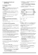
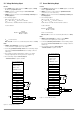
Figure 2.4 Rack Conversion for a Single Device
➂ Replace the filler strips with the 19" limit stop on one side, and
the ½19" blanking plate on the other side. Fasten the limit stop
and the blanking plate with the 4 screws.
➃ Unscrew the feet from the bottom of the device. Remove the
rubber inserts from the feet first, behind which the screws are
concealed.
➄ Install the KONSTANTER into the rack. Keep all remaining parts in
a safe place for possible future use.
➅ The KONSTANTER must be supported in the rack at one side with
slide rails. The slide rails, as well as the screws required for
securing the KONSTANTER’s front panel are rack-specific, and
must thus be obtained from your rack supplier.
Conversion for Installing Two
KONSTANTERs to a 19" Rack
Use the 19" adapter set accessory 2x32N.
It includes two 19" limit stops and one 19" joiner.
➀ Loosen the 8 screws from the front panels at the KONSTANTERs.
➁ Pull out the two filler strips from the left and right-hand sides of
the front of the side panels at each device.
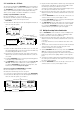
Figure 2.4 Rack Conversion for Two Devices
➂ Replace the filler strips with the 19" limit stops at the right and
left-hand sides, and with the 19" joiner in the middle. Fasten
the limit stops and the joiner with the 8 screws.
Screw the housings together at the threaded through-holes in
the cable spacers at the back of the devices.
➃ Unscrew the feet from the bottom of the devices. Remove the
rubber inserts from the feet first, behind which the screws are
concealed.
➄ If the two KONSTANTERs are to be electrically connected to one
another, use the accessory “mains jumper cable”.
➅ Install the KONSTANTERs into the rack. Keep all remaining parts
in a safe place for possible future use.
➆ The KONSTANTERs must be supported in the rack at both sides
with slide rails. The slide rails, as well as the screws required
for securing the KONSTANTER’s front panels are rack-specific,
and must thus be procured from your rack supplier.
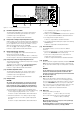
2.5 Multiple Benchtop Device Combination
Up to 3 KONSTANTERs can be stacked to create a multiple bench-
top device combination (see also chapter 5 regarding possible
electrical connections via the analog interface).
➀ Unscrew the feet from the bottom of the device. Remove the
rubber inserts from the feet first, behind which the screws are
concealed.
Four large slotted holes are now visible at the bottom of the
device.
➁ Turn the four collar screws from the device feet into the threads
at the top of the other device housing. Keep the 4 lock
washers and device feet in a safe place.
➂ Set the KONSTANTER without feet on top of the other KONSTAN-
TER. The screws from the bottom device must protrude
through the enlarged openings in the bottom of the top device.
Push the top device back slightly, until the screws snap into
place.
➃ Screw the housings together at the threaded through-holes in
the cable spacers at the back of the devices. This secures the
top device against slipping.
➄ If the two KONSTANTERs are to be electrically connected to one
another, use the accessory “mains jumper cable”.
➁
➀
➀
➁
19" Limit Stop
➃
➂
½19" Blanking Plate
19" Joiner
19" Limit Stop
➃
➃
➂