
User manual


GMC-I Messtechnik GmbH 23
5.9 Series Operation
The outputs of several devices can be connected in series if output
voltage from a single device is insufficient, or if a ± voltage needs to
be generated.
WARNING!
Maximal allowable cumulative output voltage for series connection is
120 V (or 240 V with grounded neutral).
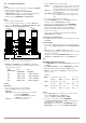
5.9.1 Direct Series Operation
CAUTION!
When outputs with different nominal values are series connected, the
highest selected current flows at all outputs in the event of short-circuit.
However, internal reverse voltage protection diodes are only rated for
nominal current at their own devices (see reverse voltage withstand under
Technical Data). All current setpoint values must therefore be set to the
lowest nominal current value of all interconnected devices. This setting is
accomplished with the Ilim parameter. A diode can also be connected in
the reverse direction between the output terminals at the device with
lower nominal values (D
e
, see figure 5.9.1 a). The diode must be capable
of conducting nominal current from the output with the highest nominal
value.
Function
• Simplest way to increase voltage to the consumer to a level greater
than that provided by a single device.
• Easy wiring
• Less suitable for constant current operation
Wiring
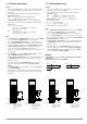
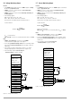
Figure 5.9.1 a Wiring for Direct Series Operation
Procedure
• Deactivate all outputs.
• Adjust current setpoint values ISET for all series connected
devices to approximately the same value:
Iset = ISET1 = ISET2 = ISET3 = ISETn
• Adjust voltage setpoint values USET such that the desired
cumulative voltage setpoint value Uset is achieved:
Uset = USET1 + USET2 + USET3 + ... + USETn
• Activate the outputs.
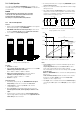
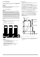
Functional Principle
• The sum of the individual output voltages is made available to the
consumer.
• If connected load resistance is continuously reduced, all
outputs deliver the same load current at first.
• If load current reaches the lowest selected current setpoint value,
current regulating is triggered at the respective output.
• If load resistance is further reduced, this output maintains a
constant load current until its output voltage has dropped to 0 V.
• Further reduction of load resistance results in negative voltage at
the respective output caused by the other outputs.
• The respective internal reverse voltage protection diode is
conductive as of approximately –0.5 V.
• Load current can now rise again until current regulating is triggered
at the output with the next highest current setpoint value.
• This process continues until load current triggers current
regulating at the output with the highest current setpoint value.
• Constant current is maintained by this final output until
short-circuiting occurs.
Figure 5.9.1 b U / I Diagram for Direct Series Connection
Note
• The outputs can be activated and deactivated simultaneously by
connecting the SIG1 outputs to the TRG inputs (see also
chapter 5.9.2).
Settings
ISET = Iset
+SENSE
-OUT
-OUT
-SENSE
Analog Interface
SIG1 OUT
SIG2 OUT
TRG IN –
TRG IN +
+ 15 V
AGND
Uset -
Uset +
Iset +
U-MON
I-MON
+OUT
+OUT
SLP-KONSTANTER
SLP-KONSTANTER
SLP-KONSTANTER
Settings
USET1+2+3 = Uset
ISET = Iset
OUTPUT ON/OFF
+SENSE
−OUT
−OUT
−SENSE
Analog Interface
SIG1 OUT
SIG2 OUT
TRG IN –
TRG IN +
+ 15 V
AGND
Uset -
Uset +
Iset +
U-MON
I-MON
+OUT
+OUT
Load
= Only required for sensing mode operation
Settings
ISET = Iset
+SENSE
-OUT
-OUT
-SENSE
Analog Interface
SIG1 OUT
SIG2 OUT
TRG IN –
TRG IN +
+ 15 V
AGND
Uset -
Uset +
Iset +
U-MON
I-MON
+OUT
+OUT
Output
Output
Output
D
e1
D
e2
D
e3
Settings
USET1+2+3 = Uset
ISET = Iset
OUTPUT ON/OFF
Settings
USET1+2+3 = Uset
ISET = Iset
OUTPUT ON/OFF
Ideal working range for
current regulation at the
consumer
Ideal working range for
voltage regulation at the
consumer
U
out1
U
out2
U
out3
I
out1
I
out2
I
out3
R
L
R
L