User Manual SECULIFE DPBASE DIGITAL PRESSURE METER 3-349-845-03 1/1.
GMC-I Messtechnik GmbH DP Base TABLE OF CONTENTS WARNINGS, CAUTIONS, NOTICES ............................................................................. ii DESCRIPTION ............................................................................................................... 1 LAYOUT ......................................................................................................................... 2 DISPLAY INDICATORS ..............................................................................
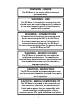
WARNING - USERS The DP Base is for use by skilled technical personnel only. WARNING - USE The DP Base is intended for testing only and should never be used in diagnostics, treatment or any other capacity where it would come in contact with a patient. WARNING - CONNECTIONS All connections to patients must be removed before connecting the DUT to the DP Base. A serious hazard may occur if the patient is connected when testing with the DP Base.
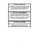
CAUTION - SERVICE The DP Base is intended to be serviced only by authorized service personnel. Troubleshooting and service procedures should only be performed by qualified technical personnel. CAUTION - ENVIRONMENT Exposure to environmental conditions outside the specifications can adversely affect the performance of the DP Base. Allow the DP Base to acclimate to specified conditions for at least 30 minutes before attempting to operate it. CAUTION - CLEANING Do not immerse.
NOTICE – SYMBOLS Symbol Description Center Negative NOTICE – ABBREVIATIONS ANSI American National Standards Institute BCD Binary Coded Decimal C cmH20 ° DUT DC Celsius Centimeter(s) water Degree(s) Device Under Test Direct Current Euro European F Fahrenheit FS Full Scale inH20 Inche(s) of water kg kilogram(s) µA microampere(s) mA milliampere(s) mBar mm milliBar(s) millimeter(s) mmHg millimeter(s) of Mercury NEDA National Electronic Distributors Association Lbs pounds PSI pounds
NOTICE – DISCLAIMER GMC-I Messtechnik GmbH WILL NOT BE RESPONSIBLE FOR ANY INJURIES SUSTAINED DUE TO UNAUTHORIZED EQUIPMENT MODIFICATIONS OR APPLICATION OF EQUIPMENT OUTSIDE OF THE PUBLISHED INTENDED USE AND SPECIFICATIONS. NOTICE – DISCLAIMER GMC-I Messtechnik GmbH RESERVES THE RIGHT TO MAKE CHANGES TO ITS PRODUCTS OR SPECIFICATIONS AT ANY TIME, WITHOUT NOTICE, IN ORDER TO IMPROVE THE DESIGN OR PERFORMANCE AND TO SUPPLY THE BEST POSSIBLE PRODUCT.
This Page Intentionally Left Blank vi
GMC-I Messtechnik GmbH DP BASE DIGITAL PRESSURE METERS The Model DP Base is a Microprocessor based Digital Pressure Meter. It measures both gas and liquid pressures and provide multiple engineering unit displays for the results. The following are highlights of some of the main features. Main Features: -13.50 TO 100.
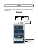
LAYOUT This section looks at the layout of the DP Base and gives descriptions of the elements that are present. DP Base Layout RS-232: ⅛” Stereo Jack Power: 2.
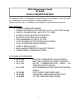
DISPLAY INDICATORS Several indicators are provided to identify the current mode and/or status. PRESSURE UNITS – Pressure units are indicated by an identifier bar. The RANGE key will toggle the pressure units among PSI, mmHG, inH2O and cmH2O. The following is a breakdown of the available pressure units and the measurement range for each: Identifier Bar (flashing) Pressure Units Range PSIG -13.50 to 100.
KEYS Several tactile-touch keys are provided for system operation. – The function of this key is dependent on the Current Operating Mode as follows: POWER OFF – If this key is pressed while the power is turned OFF, the power will be turned ON PRESSURE MEASUREMENT – If this key is pressed while the pressure is being displayed, the Setup Mode will be entered. SETUP MODE – Pressing this key while in the Setup Mode will sequence the display through the available parameters.
– The function of this key is dependent on the Current Operating Mode as follows: PRESSURE MEASUREMENT – If this key is pressed while the pressure is being displayed, the unit will display the maximum pressure detected since the capture register was last reset. SETUP MODE – If this key is pressed in the Setup Mode, the value of the displayed setting will increment. Pressing and holding this key will cause the rapid automatic incrementing of the displayed setting.
SETUP MODE The Setup Mode allows the user to adjust the configuration of the meter. The Setup Mode is entered by pressing The ON/SETUP key when the unit is on. The parameter and the current value will alternately flash in the display.
COMMUNICATIONS Since the meter does not handle a great deal of data, the RS-232 communications link has been optimized to allow the user, through very simple instructions, to control and request data from the meter. Refer to Specifications section for RS-232 Settings (Baud, etc). Data transmitted/received is in standard ASCII format, and all numerical values are in BCD format. All commands sent to the unit should be terminated with a “Carriage Return” character ( or in hexadecimal, 0x0D).
Examples: Data Sent W172 Data Returned W172 W1700002 W1700002 W01100 U - UPLOAD W01100 ?? Meaning Echo of Command Sent (Set Pressure units to “inH2O”) Echo of Command Sent (Set Pressure units to “inH2O”) Echo of Command Sent Invalid Command Response (Location 01 is Read Only) The UPLOAD command allows the user to read all of the selected device data from locations 1 through 16 with a single command.
The CANCEL command is simply a way to re-establish proper control, should a communications error occur or an incorrect command be transmitted. For the most part, an incorrect command will simply be ignored and the meter will return to listening for future commands. However, a prior command may be cancelled midstream by transmitting the CANCEL command anytime. X - CANCEL Usage: X This command does not require a carriage return, nor will it acknowledge with a carriage return.
MANUAL REVISIONS Revision # Program # Revisions Made Rev 01 Rev 02 Rev 03 Rev 04 Rev 05 Rev 06 Rev 07 Rev 08 Rev 09 DT7325CA DT7325CA DT7325CA DT7325CB DT7325CD DT7325CG DT7325CG DT7325CI DT7325CI Preliminary Manual Misc. Edits Battery Eliminator Updated Status Display Graphics Updated Accuracy Specifications Updated Program Upgrades, Color Overlays Updated Misc. Edits Format Updated, Specifications Updated, Misc.
SPECIFICATIONS PRESSURE -13.50 to 100.00 PSI -701 to 5190 mmHg @ 20 °C -374 to 2773 inH2O @ 20 °C -951 to 7043 cmH2O @ 20 °C 0.01 PSI 1 mmHg @ 20 °C 1 inH2O @ 20 °C 1 cmH2O @ 20 °C RANGE RESOLUTION MAXIMUM OVERPRESSURE ACCURACY ± 0.1% FS DIGITAL FILTER 1 – 255 samples COMPATIBLE MEDIA CONNECTIONS 200 PSI Only non-corrosive, non-ionic, or otherwise pure fluids and/or gases that are compatible with sensor materials including glass, silicon, ceramic, epoxy, RTV, gold, aluminum and nickel.
ENVIRONMENTAL OPERATING RANGE 0 to 50 °C (32 to 122 °F) STORAGE RANGE -40 to 60 °C (-40 to 140 °F) ELECTRICAL 9V Alkaline (ANSI/NEDA 1604A or equivalent) BATTERY 9 V, 50 mA DC BATTERY ELIMINATOR POWER CONSUMPTION BATTERY LIFE RS-232 COMMUNICATIONS 20-21100 (USA Version) 20-21101 (Euro Version) ON < 15 mA OFF < 40 A CONTINUOUS 80 hours OFF 1 year BAUD 115200 DATA BITS 8 START BITS 1 STOP BITS 1 PARITY none HANDSHAKING none CONNECTIONS 1/8 Stereo Receptacle for use with 20-21102
NOTES 13
NOTES 14
NOTES 15
GMC-I Messtechnik GmbH Südwestpark 15 90449 Nürnberg Germany FON: +49 911 8602-111 FAX: +49 911 8602-777 www.gossenmetrawatt.com sales@gossenmetrawatt.com DP Base User Manual 1/1.