
Datasheet
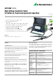

METRISO PRIME
High-Voltage Insulation Tester
for battery or hand crank generator operation
2 GMC-I Messtechnik GmbH
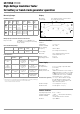
Measuring Ranges
Insulation Resistance
ShortCircuit Current I
K
1.3 mA
Making Capacity for Insulation Resistance Measurement
Response Time < 100 G <3s; >100G <8s
also valid for test voltage or measuring
range changes
Direct and Alternating Voltage
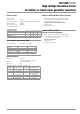
Protective Devices
1)
with reference to scale length 97.5 mm (100 M range) or 109.8 mm (1 Trange)
2)
PTC resistor cool-down period until start of new measurement:
at least 2 minutes must be observed!
Display
Movement Core-magnet moving-coil mechanism
Scale length 111.5 mm (longest scale)
Reference Conditions
Ambient
Temperature + 23 C 2K
Relative Humidity 40 ... 60%
Meas. Quantity
Frequency 50 Hz 10 Hz
(for voltage measurements)
Line Voltage
Waveform Sine, deviation between effective
and rectified value < 1%
Battery voltage 8 V1%
Operating position Horizontal
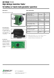
Power Supply
Standard or
Storage Battery 6 ea. 1.5 V single cell per IEC R20
(6 x D-Size)
Working Range 6 V ... 10 V
Battery Service Life 7500 measurements for test voltage of
1000 V with meas. resistance of 1 M,
15000 measurements for test voltage
of 500 V with meas. resist. of 500 k,
measurement of 5 s – pause 25 s
Crank Generator (optional) 2 to 3 r.p.s. with moderate strength,
the LED signals sufficient crank
frequency and consequently the vali-
dity of measuring values
Nominal Voltage 7.5 V (at approx. 2.5 r.p.s.)
Nominal Power 4 W (at approx. 2.5 r.p.s.)
Ambient Conditions
Operating Temperature 0 C ... + 40 C
Storage Temperature 20 C ... + 60 C (without batteries)
Relative Humidity max. 75%,
condensation must be avoided
Elevation up to 2000 m
Scale/
Stan-
dard
Mea-
suring
Range
Nominal
Range of
Use
Nominal/Test
Voltage
U
N
/ U
T
Nom./Test
Current
I
N
/ I
T
Intrinsic
Uncer-
tainty
1)
Measuring
Uncer-
tainty
VDE0413
100 k
...
100 M
100 k
... 10 M
100 V
250 V
500 V
1000 V
1mA
2.5%
30%
of measu-
red value
10 k
... 1 T
100 k
...
100 G
100/1500 V
250/
2000 V
500/
2500 V
1000/5000 V
1mA/0.7mA
1mA/0.5mA
1mA/0.4mA
1mA/0.1mA
5%
Measuring range Frequency Internal
resistance
Max. allowable
voltage
Intrinsic error
1)
0 ... 2000 V AC/DC 15 ... 500 Hz 5 M 2200 V AC/DC
max. 10 s
5%
Terminal Internal
Resistance
Max. Allowable
Voltage
Protective Device
–Measurement
cable
—
to +meas. cable/
to Guard cable:
2000 V DC/AC
max. 10 s
via grounded damping
diodes
+Measurement
cable
Insulation
measurement
—
to –meas. cable/
to Guard cable:
2000 V DC/AC
max. 10 s
Diodes in high-voltage
cascade,
PTC thermistor
2)
and
series resistors
Guard cable
between Guard
and meas. cables
90 k
to meas. cable
2000 V DC/AC
max. 10 s
PTC thermistor
2)
and
series resistors
Battery — 10 V
Pole protection with diodes
voltage limiting in battery
charger (optional)
1
2
1
2