
Operation Manual


Table Of Contents
GMC-I Messtechnik GmbH 9
380 kΩ at an operating voltage of 380 V.
In order to assure that the
insulation resistance limit values
specified in the applicable
standards are not exceeded,
maximum measuring error of the
measuring instrument must be
taken into consideration. The
required minimum display values
for various limit values are listed in
the following table. Intermediate
values can be interpolated in a
linear fashion.
Test Voltages
During measurement of insulation resistance, a test voltage U is applied
to the device under test, which lies between the nominal voltage U
N
selected with the rotary switch (3), and open-circuit voltage U
0
:
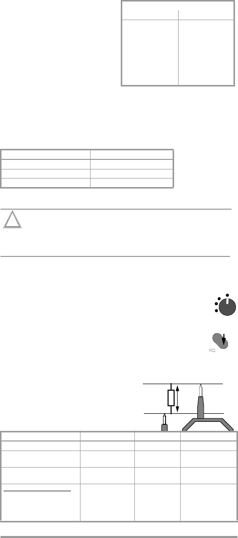
4.3 Low-Resistance Measurement (VDE 0413, part 4 / EN 61557, part 4)
Attention!
!
Resistance measurements may only be performed on
voltage-free devices under test, because interference
voltages distort measurement results.
Adhere to the prescribed sequence:
Ð Make sure that the device under test is voltage-free in
accordance with chapter 4.1.
Ð Set the rotary switch to Ω.
Ð Contact the device under test with the test probes (1:
positive pole of the 200 mA constant current source
and 8: negative pole of the constant current source).
Ð Measurement is performed for as long as the toggle
switch is held in the Ω position. Observe the LED.
Read the measured value from the scale within a
range of 0 to 4 Ω. It is advisable to perform a second
measurement with reversed polarity in order to eliminate
semiconductor circuits.
Ð
End the measurement by
releasing the toggle switch.
Ð
Remove the test probes from
the device under test.
U
N
Position at Rotary Switch (3) Test Voltage at DUT
100 V 100 V < U < 110.8 V
250 V 250 V < U < 277.0 V
500 V 500 V < U < 554.0 V
Low Voltage Scale LED Beeper
measured value ≤ 2 Ω value is displayed green continuous signal
2 Ω < measured value ≤ 4Ω value is displayed green periodic sequence
of signals
measured value ≥ 4Ω pointer oscillates green blinks periodic sequence
of signals
measurement not possible:
– battery voltage too low
– rotary or toggle switch
not adjusted correctly
pointer oscillates
pointer oscillates
red
green blinks
no signal
no signal
* Minimum display values for
insulation resistances with specified
limit values in consideration of
maximum measuring error.
MΩ Range
Limit value Min. Display *
0.10 MΩ
0.25 MΩ
0.40 MΩ
0.50 MΩ
0.60 MΩ
0.70 MΩ
0.80 MΩ
1 MΩ
2 MΩ
0.130 MΩ
0.325 MΩ
0.520 MΩ
0.650 MΩ
0.780 MΩ
0.910 MΩ
1.040 MΩ
1.300 MΩ
2.600 MΩ
Ω
500 V
250 V
100 V
Ω
MΩ
V
R
x
Voltage Drop