
Datasheet

METRAHITT-COM PLUS
Cable Multimeter for Measurements
in Symmetrical Copper Cable Networks
4 GMC-I Messtechnik GmbH
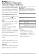
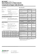
Measurements on Cables (a-b) (a-E) (b-E)
Insulation Resistance Measurement in Selector Switch Positions (a-b) (a-E) (b-E)
1)
1)
During insulation resistance measurement (
M
@UISO
): If
ERROR is displayed as
„Error“
>> limits:
U
interference
> 10 ... 20 V and U
interference
U
ISO
, Ri < 10 k@ Uiso 10 V,
Ri < 100 k @ Uiso 100 V
2)
Interference voltage measurement TRMS (V AC + DC) with 120 k input resist-
ance, bandwidth 15 Hz ... 500 Hz, measuring error 3% + 30 Digit
Ripple voltage < 4 Vss 50 Hz, parallel capacitance < 3 μF
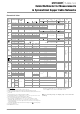
Interference-immune Capacitance Measurement in Selector Switch
Positions (a-b) (a-E) (b-E)
Measuring voltage U
0
= 2 Vss approx. 1 Hz, parallel resistance > 5 M
Ripple voltage < 4 Vss 50 Hz
Galvanic Signature Ascertainment in Selector Switch Positions (a-b)
Prerequisites:
Parallel resistance > 200 k, parallel capacitance < 1 μF,
Ripple voltage < 4 Vss 50 Hz
and exclusively high-resistance DC voltage
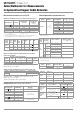
Response Time (after manual range selection)
Influencing Quantities and Influence Error
1)
With zero balancing
2)
Power limiting: frequency x voltage max. 6 x 10
6
V x Hz
3)
The accuracy specification is valid as of a display value of 10% to 100% of the
measuring range for both measuring modes with the TRMS converter in the A AC
and A (AC+DC) ranges.
4)
Except for sinusoidal waveshape
Measuring Range Resolution
Nominal Voltage
U
ISO
(U
INS
)
Intrinsic Error
under Reference
Conditions
(% rdg + d)
6 V ... 110 V
2)
0.1 V
Ri
approx.
120 k
3 + 30
5 ... 310.0 k 0.1 k 10//100 V 3 + 5
0.280 ... 3.100 M 1 k
10
//100 V
3 + 5
02.80 ... 31.00 M 10 k
10
//100 V
5 + 5
028.0 ... 310.0 M 100 k
10
//100 V
5 + 5
Measuring
Function
Switch
Setting
Nom.
Voltage
U
N
@100k
Open-
Circuit
Voltage
U
o
Nom.
Cur-
rent I
N
@100k
Short-
Circuit
Cur-
rent I
k
Acoustic
Signal
for
Overload Capacity
Value Time
U
interference
/
M
ISO
— —— —
U > 110
V
110 V Cont.
M
ISO
100 V Max.
120 V
> 1.0
mA
<1.2
mA
U > 110
V
100 V
10 s
8.7 V 11 V 0.09 < 0.260 U > 110V 100 V 10 s
Measuring
Range
Resolution
3100/1100
Digit
Intrinsic Uncertainty under
Reference Conditions
( ... % rdg. + ... d)
Measuring
Cycle (max.)
Overload
Capacity
300 nF 100 pF 2 + 10 2 s
600 V / PTC
max. 10 s
3 μF 1 nF 2 + 10 2 s
10 μF 10 nF 5 + 10 2 s
Signature if interference value is stable in range plus decision value
available
–50% ... +30%
approx. +60% ... +200%
not available
< +20%
Measured Quantity /
Measuring Range
Response Time,
Digital Display
Measured Quantity
Waveshape
V, V
A, A
1.5 s
from 0 to 80%
of upper range limit value
300 ... 3 M 2s
from to 50%
of upper range limit value
30 M 5s
Continuity < 50 ms
C (Pt 100) Max. 3 s
1.5 s
30 nF ... 300 FMax. 5s
from 0 to 50%
of upper range limit value
>10 Hz 1.5 s
Influencing
Quantity
Sphere of
Influence
Measured Quantity /
Measuring Range
1)
Influence Error
(...% rdg. + ... d) / 10 K
Temperature
0C ... +21 C
and
+25 C... +40 C
V 0.2 + 5
V 0.4 + 5
300 ... 3 M 0.5 + 5
30 M 1 + 5
mA/A 0.5 + 5
mA/A 0.8 + 5
30 nF ... 300 F1 + 5
Hz 0.2 + 5
C/F (Pt100/Pt1000) 0.5 + 5
Influ-
encing
Quan-
tity
Measured
Qty. / Measur-
ing Range
Sphere of Influence
Intrinsic uncertainty
3)
... % rdg. + ... d)
Fre-
quency
V
AC
2)
300 mV
...
300 V
> 15 Hz ... 45 Hz
3 + 5 > 300 digits
> 65 Hz ... 10 kHz
600 V > 65 Hz ... 5 kHz 3 + 5 > 60 digits
A
AC
300 A
...
1 A
> 15 Hz ... 45 Hz
3 + 10 > 300 digits
> 65 Hz ... 10 kHz
A
AC
+
DC
300 A
...
1 A
> 15 Hz ... 45 Hz
3 + 30 > 300 digits
> 65 Hz ... 10 kHz
A
AC
300 mV /
3 V / 30 V
> 65 Hz ... 10 kHz 3 + 5 > 300 digits
Influencing
Quantity
Sphere of
Influence
Measured Quantity /
Measuring Range
Influence Error
4)
Crest Factor CF
1 ... 3
V, A
1% rdg.
> 3 ... 5 3% rdg.
Influencing
Quantity
Sphere of
Influence
Measured Quantity Influence Error
Relative
humidity
75%
3 days
instrument off
V A, , F, Hz, C 1 x intrinsic uncertainty
Battery voltage 1.8 to 3.6 V ditto
Included in intrinsic uncer-
tainty
Line operation 5 V ditto 10 digit
Influencing
Quantity
Sphere of Influence
Measured Quantity /
Measuring Range
Damping
Common mode
interference
voltage
Interference quantity max. 600 V V > 120 dB
Interference quantity max. 600 V
50 Hz ... 60 Hz, sine
3 V , 30 V > 80 dB
300 V > 70 dB
600 V > 60 dB
Series mode
interference
voltage
Interference quantity: V ,
respective nominal value of the
measuring range,
Max. 600 V , 50 Hz ... 60 Hz sine
V> 50dB
Interference quantity max. 600 V V > 110 dB