
Datasheet

METRAHITT-COM PLUS
Cable Multimeter for Measurements
in Symmetrical Copper Cable Networks
2 GMC-I Messtechnik GmbH
Insulation Resistance Measurement with Interference Voltage Display in
Switch Positions (a-b) (a-E) (b-E) with Adjustable Test Voltage 10 V/100 V
Whether insulation testing will be conducted between E-a, b-E or
a-b can be selected by turning the selector switch to the appro-
priate position. If the instrument detects interference voltage of
greater than 15 V AC or 25 V DC during insulation testing, an
error message is briefly displayed at the LCD panel. The instru-
ment is then automatically switched to voltage measurement, and
the currently measured voltage value is displayed.
Interference-immune Capacitance Measurement in Selector Switch
Positions (a-b) (a-E) (b-E)
Asymmetry can be directly ascertained by means of capacitance
measurement in switch positions a-b-E. In contrast to the capaci-
tance measurement in switch position , the measured value is
only affected to a minor degree by line interference and/or parallel
resistance with this capacitance measurement method.
Error Localization (with Capacitance Measurement and Cable Length
Comparison)
Interruption of a single core or contact with an open-circuit core
(capacitive asymmetry) can be recognized at the display by
quickly reversing test voltage polarity.
The conductor is good if the bar graph lengths are the same in
the a-E and b-E selector switch positions.
Cable Length Measurement
Bar graph length is directly proportional to cable length.
Capacitance per meter also appears as a digital display.
Automatic Storage of Measured Values
The DATA HOLD function automates the storage of measured values
after they have settled in. A patented process assures that random
values are not saved to memory in the case of rapidly changing mea-
sured quantities, but rather the actual measured value. The stored
measured value appears at the digital display. The analog display
continues to read out the current measured value.
Overload Protection
The instrument is safeguarded for up to 600 V in all measuring
functions by overload protection. Voltage of greater than 620 V
and current of greater than 1.2 A are indicated acoustically.
FUSE appears at the display if the fuse for the current measuring
input blows.
Battery Charging Status – Power Saving Circuit
The battery charging status is indicated by means of four sym-
bols. The device is switched off automatically if the measured
value remains unchanged for a period of between 10 and 59 min-
utes (adjustable), and if none of the controls are activated during
this time. Automatic shutdown can be deactivated by switching
the instrument to continuous operation.
Infrared Data Interface
The device can be remote configured, and momentary and saved
measurement data can be read out via the bidirectional infrared
interface. The USB X-TRA interface adapter and METRAwin 10
software are required to this end (see accessories). Interface
protocol and device driver software for LabVIEW
®
(National
Instruments™) are available upon request.
DAkkS calibration certificate
METRAHIT T-COM PLUS
cable
multimeters are furnished with an
internationally valid DAkkS calibration certificate (recognized by
EA and ILAC). After the specified calibration interval has elapsed
(recommended interval: 1 to 3 years), the multimeters can be
inexpensively recalibrated in our own DAkkS calibration labora-
tory.
Voluntary Manufacturer’s Guarantee
36 months for materials and workmanship
1 to 3 years for calibration (depending upon application)
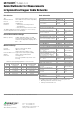
Applicable Regulations and Standards
Included
1 cable multimeter
1 protective rubber cover
1 KS21T cable set (600 V CAT III) consisting of:
1 two-conductor measurement cable (yellow/blue),
2 meters long with test probes, 1 earth terminal cable (black),
2 meters long with test probe
1 condensed operating instructions, English/German
– detailed operating instructions are available for download on
the Internet at www.gossenmetrawatt.com
1 DAkkS calibration certificate with calibration report
2 batteries, 1.5 V, type AA, installed
DIN EN 61010, part 1/
VDE 0411-1
Safety requirements for electrical equipment for
measurement, control and laboratory use
DIN EN 61326-1
VDE 0843-20-1
Electrical equipment for measurement, control and laboratory
use – EMC requirements –
Part 1: General requirements
DINEN60529
VDE 0470, part 1
Test instruments and test procedures
– degrees of protection provided by enclosures (IP code)
TS 0293/96 Technical specifications set forth by Deutsche Telekom
– Cable multimeters for measurements in symmetrical
copper cable networks