
Operation Manual


16 GMC-I Messtechnik GmbH
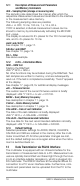
12.1 Description of Measurement Parameters
and Memory Commands
rAtE – Sampling Rate (storage or measuring rate)
The sampling rate determines the interval, after which the
respective measurement values are transmitted to the interface
or the measurement value memory.
The following sampling rates are possible:
rAtE ↵ OFF, 10 ms, 100 ms, 1 s, 10 s, 60 s.
If OFF is selected, individual measurement values can be
stored to memory by simultaneously activating the ESC|FUNC
and ↵ keys.
The display is reduced to 5½ places for the 100 ms sampling
rate, and to 4½ places for 10 ms.
Addr and rS232
See chapter 13.1, page 17.
SEnSor and tEMP
See chapter 10, page 12.
FILt – Filter
See above example.
12.2 InFo – Information Menu
tESt – RAM Test
Starting the RAM test:
rAtE InFO ↵ tESt ↵
No other functions may be activated during the RAM test. Two
test samples are written to memory, and are subsequently
read out. If the test is completed successfully, “Good” appears
at the display.
See chapter 17, page 26, for additional display messages.
uEr – Firmware Version
The revision level of the current firmware version is briefly
displayed: rAtE InFO ↵ uEr ↵ 070102.
MEM – Query Memory Occupancy
See description in chapter 11, page 14.
CLEAr – Delete Memory Content
See description in chapter 11, page 14.
CALdAtE – Date of Last Calibration
The date of the last calibration is briefly displayed:
rAtE InFO ↵ CALdAtE ↵ 020399.
CALdUE – Next Recommended Calibration
The due date for the next recommended calibration is briefly
displayed: rAtE InFO ↵ CALdAtE ↵ 020300.
12.3 Default Settings
Selected parameter settings for ADDR, RS232, CALDATE,
CALDUE and VER are retained in the memory after the multi-
meter is switched off. All other parameter changes are lost,
and the default settings are once again active when the instru-
ment is switched back on.
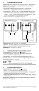
13 Data Transmission via RS232 Interface
The multimeter is equipped with an infrared interface for the
transmission of measurement data to a PC. Measurement val-
ues are optically transmitted via infrared light through the hous-
ing to an interface adapter (accessory), which is plugged into
the multimeter. The RS232 interface at the adapter allows for
connection to a PC via an interface cable. Furthermore, com-
mands and parameters can be uploaded from the PC to the
multimeter.