
Operation Manual


12 GMC-I Messtechnik GmbH
10 Temperature Measurement
10.1 Temperature Measurement with Pt100 and Pt1000
Ð Enter the type of sensor to be used (Pt100 or Pt1000) in the
menu mode:
rAtE SEnSor ↵ Pt 100 Pt 1000 ↵
Ð Set the selector switch to
“°C
2
” for 2-wire measurement connection or
“°C
4
” for 4-wire measurement connection.
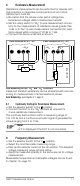
Ð Connect the sensor as shown in the following diagram:
The instrument displays the measured temperature in the unit
of measure entered in the menu mode (parameter: “tEMP”).
Compensating for Cable Resistance and Offset
Due to high measuring resolution, compensation must be
made for offset and cable resistance in the order indicated
below, especially for the 2-wire resistance temperature
measuring function (“°C
2
”
):
– Offset
Any remaining influence caused by the cables and contact
resistance can be eliminated by means of zero balancing (see
chapter 6.1, page 9).
– Cable Resistance
• Default setting: A preset cable resistance value is
compensated for when the default setting is used. The
preset value is 0.1 Ω which is suitable for temperature
sensors available as accessories.
• Entering a value other than the preset cable resistance value:
(value from data sheet or user calculated, see below):
Enter the utilized sensor type (Pt100 or Pt1000) and the
cable resistance value in the “Setup” menu (range: 00.01
to 99.99 Ω):
rAtE SEnSor ↵ Pt 100 (Pt 1000) ↵
Lr (lead resistance) ↵ XX.XX Ω ↵
• Calculating cable resistance:
í Heat or cool the sensor to a known temperature (e.g.
0 °C in ice water), and adjust the value in the Lr menu
until the correct measured value is displayed.
4-Wire Connection2-Wire Connection
Possible Sensors:
Z3409
TF550
TF220
TS Chipset
ϑ
–
°
C
2
+
–
°
C
2
+–
°
C
4
+