
Operation Manual


GMC-I Messtechnik GmbH 11
GB
8 Resistance Measurement
Resistance measurements can be performed for devices with
high inductive or capacitive components such as motors,
transformers, coils etc.
Ð Be certain that the device under test is voltage-free.
Extraneous voltages distort measurement results!
Ð Set the rotary switch to “Ω
2
” (2-wire measurement connec-
tion) for the measurement of resistance values greater than
1kΩ, or to “Ω
4
” (4-wire measurement connection) for resis-
tance values within a range of 100 Ω to 1 kΩ.
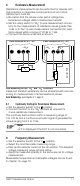
Ð Connect the device under test as shown.
Zero Balancing for the “Ω
2
” and “Ω
4
” Functions
Cable and transition resistance can be eliminated with zero bal-
ancing for measurements of small resistance values.
Zero Balancing, see chapter 6.1, page 9
8.1 Continuity Testing for Resistance Measurement
Ð Set the selector switch to the position.
Ð Connect the DUT to the “Ω
2
” sockets as required for
2-wire resistance measurement.
The continuity test functions within a measuring range of
0to100Ω, and a continuous acoustic signal is generated for
values ranging from 0 to 10 Ω.
Note!
„0.L“ is displayed if the DUT is not connected.
9 Frequency Measurement
Ð Set the selector switch to the V position.
Ð Select the most favorable measuring range.
Ð Now set the selector switch to the Hz position. The selected
voltage measuring range remains active.
Ð Apply the measured quantity in the same way as for voltage
measurement.
Measurable frequencies and allowable voltages can be found
in chapter 15, page 18.
R
x
4-Wire Connection for Rx
≤
1 k
Ω
2-Wire Connection for Rx
≥
1 k
Ω
–
Ω
2
+
R
x
Current Path
–
Ω
4
+
–
Ω
2
+