Operating Instructions METRAHIT⏐30M Precision Digital Multimeter 3-348-978-02 9/3.
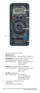
1 2 3 4 5 6 7 7 8 1 LCD display, see page 3 for description 2 MENU/ON|OFF key Menu Operating Mode: Entry acknowledgment (ENTER or ↵) 3 AVE/MIN|MAX key for storage of MIN or MAX values, as well as for displaying time since beginning of recording Menu Operating Mode: selection of individual parameters, reverse flux direction, increase values 4 MAN|AUTO key for manual measuring range selection Menu Operating Mode: selection of individual parameters, forward flux direction, reduce values 5 ESC|FUNC
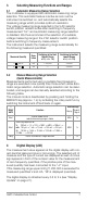
2 3 ON 4 MANDATA MIN 5 6 MAXt ON EVENTS DC AC kHz IukΩ 1 mVA 7 MΩ o 15 14 o C F IuF nF ZERO AVE MENU MEM % FULL REM FILT 13 12 11 10 9 8 Digital Display Symbols 1 Digital display with decimal place and polarity 2 Continuous operation 3 Manual measuring range selection 4 MIN value storage 5 MAX value storage 6 Selected current and voltage type 7 Unit of measure 8 Filter active 9 Message: measurement value memory is full 10 Percentage memory full 11 Memory mode active 12 Menu operating mode ac
Table of Contents Page 1 Safety Features and Precautions .................................... 5 2 Initial Start-Up ................................................................. 6 3 3.1 3.2 Selecting Measuring Functions and Ranges ................... 7 Automatic Measuring Range Selection ................................ 7 Manual Measuring Range Selection (Quick Measurements) .. 7 4 Digital Display (LCD) ........................................................
1 Safety Features and Precautions You have selected an instrument which provides you with a high level of safety. This instrument fulfills the requirements of the applicable European and national EC guidelines. We confirm this with the CE marking. The relevant declaration of conformity can be obtained from GMC-I Messtechnik GmbH. The multimeter has been manufactured and tested in accordance with safety regulations IEC/EN 61010–1:2010/ VDE 0411–1:2011.
Errors and Extraordinary Strains If it may be assumed that the instrument can no longer be operated safely, it must be removed from service and secured against further use. Safe operation can no longer be relied upon • if the instrument demonstrates visible damage, • if the instrument no longer functions, • after a long period of storage under unfavorable conditions. 2 Initial Start-Up Batteries Batteries have already been installed to your instrument, and it is ready for operation. Refer to chapter 16.
3 Selecting Measuring Functions and Ranges 3.1 Automatic Measuring Range Selection The multimeter is equipped with automatic measuring range selection. This automatic feature is active as soon as the instrument is switched on, and automatically selects the measuring range which provides optimum resolution. The voltage measuring range selected in the V AC selector switch position remains active after switching to frequency measurement “Hz”, and automatic measuring range selection is disabled.
5 Minimum and Maximum Value Storage “MIN/MAX” with Time Stamp Minimum and maximum measurement values can be stored to memory with the MIN/MAX function. The most important application for this function is the determination of minimum and maximum values during long-term observation of measurement values. It can be activated for all measuring functions. Ð Apply the measured quantity to the instrument. Ð Select the measuring range with MAN|AUTO. Ð Activate the MIN/MAX function.
6.1 Zero Balancing (for V , mA , Ω and °C) Ð Select the desired measuring range with the MAN|AUTO key. Ð 2-Wire Resistance Measurement, Current Measurement or Temperature Measurement with Pt100 or Pt1000: short-circuit the positive and negative poles of sockets „mAΩ2“ or „°C2“, respectively. Voltage Measurement, Temperature Measurement with Thermocouple or 4-Wire Resistance Measurement: short-circuit the positive and negative poles of sockets „V/°CTC“ or „ΩSense“, respectively.
7 Current Measurement Ð First disconnect supply power to the measuring circuit or the load component, and discharge any capacitors which may be present. Ð Set the selector switch to “mA”. After this selection has been made with the rotary switch, the DC current mode is always active. Ð Select the current type, either “DC” or “AC+DC”, which corresponds to the measured quantity by briefly pressing the multifunction key. Double check for correct current type at the LCD.
8 Resistance Measurement Resistance measurements can be performed for devices with high inductive or capacitive components such as motors, transformers, coils etc. Ð Be certain that the device under test is voltage-free. Extraneous voltages distort measurement results! Ð Set the rotary switch to “Ω2” (2-wire measurement connection) for the measurement of resistance values greater than 1 kΩ, or to “Ω4” (4-wire measurement connection) for resistance values within a range of 100 Ω to 1 kΩ.
10 Temperature Measurement 10.1 Temperature Measurement with Pt100 and Pt1000 Ð Enter the type of sensor to be used (Pt100 or Pt1000) in the menu mode: rAtE SEnSor ↵ Pt 100 Pt 1000 ↵ Ð Set the selector switch to “°C2” for 2-wire measurement connection or “°C4” for 4-wire measurement connection.
í Heat or cool the sensor to a known temperature (e.g 0 °C in ice water), and measure the sensor’s resistance with the Ω2 function using the 1 kΩ range for Pt100 sensors, and the 10 kΩ range for Pt1000 sensors. Cable resistance is equal to the difference between the setpoint (100 Ω from DIN table) and the measured value. 10.2 Temperature Measurement with Thermocouple and Reference Junction Ð Enter the type of thermocouple to be used (J or K) in the menu mode: rAtE SEnSor ↵ ...
11 Storing Measurement Values to Memory The instrument is equipped with a quartz-movement synchronized measurement-value memory (128 kB), which has sufficient capacity for 30000 measurement values. Data can be stored to intermediate memory, or transmitted directly to a PC. Memory content can only be read out with the help of a PC, an infrared adapter and METRAwin10/METRAHit analysis software (see chapter 14, page 17).
Ð After the desired parameter has been selected, the various possible setting can be called up by activating the ↵ key. Ð The desired value can be selected by repeatedly activating the key. Ð Acknowledge with the ↵ key and return to operation in the measuring mode. Ð Entry can be interrupted by pressing the ESC|FUNC key, after which “rAtE” appears at the display. If the ESC|FUNC key is activated once again, the instrument is returned to operation in the measuring mode.
12.1 Description of Measurement Parameters and Memory Commands rAtE – Sampling Rate (storage or measuring rate) The sampling rate determines the interval, after which the respective measurement values are transmitted to the interface or the measurement value memory. The following sampling rates are possible: rAtE ↵ OFF, 10 ms, 100 ms, 1 s, 10 s, 60 s. If OFF is selected, individual measurement values can be stored to memory by simultaneously activating the ESC|FUNC and ↵ keys.
For example: • Select and read out measuring parameters • Select measuring function and range • Start measurement • Read out measurement values (online readout with simultaneous measurement: shortest possible sampling period is 100 ms) The interface is always active if the instrument is switched on. 13.1 Selecting Interface Parameters Addr – Address If several multimeters, interfaces or memory adapters are connected to the PC, each device requires its own address.
15 Characteristic Values Measuring Function V mA Ω Ω Measuring Range 100 1 10 100 600 100 1 10 100 100 1 10 100 1 10 mV V V V V μA mA mA mA Ω kΩ kΩ kΩ MΩ MΩ 100 Ω Resol. at Meas. Range Upper Limit 1200 000 1) 120 000 1) 12 000 1) 0.1 μV 1 μV 10 μV 1 μV 10 μV 100 μV 10 μV 100 μV 1 mV 100 μV 1 mV 10 mV 1 mV 10 mV 100 mV 100 pA 1 nA 10 nA 1 nA 10 nA 100 nA 10 nA 100 nA 1 μA 100 nA 1 μA 10 μA 0.1 mΩ 1 mΩ 10 mΩ 1 mΩ 10 mΩ 100 mΩ 10 mΩ 100 mΩ 1 Ω 0.
Measuring Range Intrinsic Uncertainty at max. Resolution at Reference Conditions ±(...% of rdg. + % of range) 4) 5) 100 mV 0.005 + 0.0006 6) 1 V 0.0030 + 0.0004 10 V 0.0030 + 0.0004 100 V 0.0030 + 0.0006 600 V 0.0040 + 0.0010 Frequency Range in Hz 0.08 + 0.06 7) 0.1 + 0.1 5 + 0.5 0.08 + 0.06 7) 0.1 + 0.1 0.2 + 0.1 5 + 0.5 45 … 65 10 … 1 k 1k…5k 45 … 65 15 … 1 k 10 … 10 k 10 k … 50 k 0.08 + 0.06 0.1 + 0.1 0.2 + 0.1 1 + 0.1 3 + 0.1 45 … 65 15 … 1 k 10 … 10 k 10 k … 50 k 50 k … 100 k 0.08 + 0.
Influence Variables and Effects Influence Variable Temperature Influence Variable Influence Range 0 °C ... +21 °C and +25 °C ... +40 °C Influence Range Measured Quantity / Measuring Range 1) Influence Effect ppm/K V 8 V 100 mA 20 mA 100 100 Ω ... 100 kΩ 8 1 MΩ 15 10 MΩ 100 Hz 50 °C 15 Measured Quantity / Measuring Range 1) Influence Effect Crest factor CF > 3 ... 5 V ±0.5% of rdg. , mA ±2% of rdg. 10 Measurement Quantity Waveform 3) ±0.2% of rdg. 1 ...
Reference Conditions Ambient Temperature Relative Humidity Measurement Quantity Frequency Measurement Quantity Waveform Battery Voltage Power Pack Voltage +23 °C ±2 K 40 ... 60% 45 ... 65 Hz sine 3 V ±0.1 V 5 V ±0.2 V Response Time After Manual Range Selection at max. Resolution Measured Quantity / Measuring Range V A ,V ,A , Response Time Measured Quantity Step Function max. 2 s from 0 to 80% of measuring range upper limit 100 Ω ... 1 MΩ max. 2 s 10 MΩ max.
Power Supply Batteries 2 AA size batteries alkaline manganese cells per IEC LR6 Service Life Measuring Function (with 2.5 Ah alkaline manganese cells) Power Consumption in mA Service Life in Hours V DC, mA DC, °C/°F 100 16 V (AC + DC), mA (AC + DC) 105 15 Transmission mode, sampling rate: 100 ms 9600 baud 114 19200 baud 108 Transmission mode, sampling rate: 10 ms 9600 baud 19200 baud Battery Test 156 146 Automatic display of “ ” when battery voltage falls to below approx. 2.3 V.
Ambient Conditions Operating Temp. Storage Temperature Relative Humidity Elevation Deployment Warm-Up Time Mechanical Design Protection − 5 °C ... +50 °C −25 °C ... +70 °C (without batteries) max. 75%, no condensation allowed to 2000 m indoors, outdoors: only in the specified ambient conditions 5 min. instrument: IP 50, connector jacks: IP 20 Extract from table on the meaning of IP codes IP XY (1st digit X) 2 5 Protection against foreign object entry ≥ 12.5 mm dia.
16 Maintenance – Recalibration ! Attention! Disconnect the instrument from the measuring circuit before opening to replace batteries! 16.1 Batteries Note! Battery Replacement Stored measurement values are deleted when the battery is replaced. We recommend connecting the power pack, or uploading data to a PC with the help of METRAwin10/METRAHit software, before replacing batteries in order to prevent data loss. Operating parameters remain in memory.
16.2 Power Pack Use only the NA HIT 2X power pack for power supply to your instrument. The highly insulated cable assures safety for the operator, and the power pack provides for reliable electrical isolation. When a mains power pack is used, the batteries inside the instrument are disconnected automatically. Country Germany Type Article No. NA HIT 2X Z218H Note! We recommend that zero balancing be performed in accordance with chapter 6.1, page 9, if the power pack is used. 16.
16.5 Device Return and Environmentally Compatible Disposal The instrument is a category 9 product (monitoring and control instrument) in accordance with ElektroG (German Electrical and Electronic Device Law). This device is subject to the RoHS directive. Furthermore, we make reference to the fact that the current status in this regard can be accessed on the Internet at www.gossenmetrawatt.com by entering the search term WEEE.
18 Repair and Replacement Parts Service Calibration Center * and Rental Instrument Service If required please contact: GMC-I Service GmbH Service Center Thomas-Mann-Strasse 20 90471 Nürnberg • Germany Phone +49 911 817718-0 Fax +49 911 817718-253 E-mail service@gossenmetrawatt.com www.gmci-service.com This address is only valid in Germany. Please contact our representatives or subsidiaries for service in other countries.
20 Product Support If required please contact: GMC-I Messtechnik GmbH Product Support Hotline Phone +49 911 8602-0 Fax +49 911 8602-709 E-Mail support@gossenmetrawatt.com DAkkS Calibration Certificate Reprints If you need to order a reprint of the DAkkS calibration certificate for your instrument, please include the ID number shown in the uppermost and lowermost fields of the red calibration seal. We do not need the instrument’s serial number.